Basic ASSA Aperio Lock Configuration in Doors.NET
1.0 Introduction
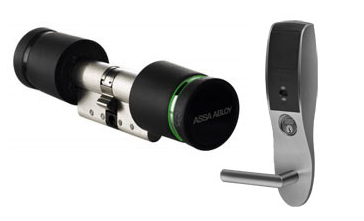
Doors.NET provides support for several Assa Abloy wireless locks featuring Aperio technology and both wireless and wired IP Locks. These locks can be used with or without hard-wired Keri controller-managed doors on the same system, providing you with the utmost in deployment flexibility.

- The Aperio AH30 Generation 5 hubs are ONLY supported with Mercury MP controller types.
- If using an AH30 Generation 5 hub (on an MP series controller) you MUST select Aperio as the protocol for the RS485 port (TB1501 or TB1500).
- TLS encryption for the Mercury controllers should be disabled unless you have loaded an SSL certificate onto the controller.
Each lock requires a hub for its wireless link, the hub connects into a bus of an Mercury-Powered NXT controller. Each controller can manage up to 16 Aperio hubs/locks.

This section provides information regarding the setup process in Doors.NET, adding the relevant lock or hub type, and addressing information for the hub.
Installers and integrators who wish to use the Aperio range of products with Doors.NET MUST be certified by ASSA Abloy. Keri Systems DOES NOT supply or support the software application which is required to configure the wireless locks. Keri Systems recommends that you contact your local ASSA Abloy supplier for further details about product training and support.
2.0 System Requirements
- Doors.NET software must be at the latest version (currently v6.0.0).
- The number of Aperio readers must be enabled on the license.
- The number of Aperio readers per controller must be enabled.
- The locks must already be paired to the hubs prior to setting up in Doors.NET.
3.0 System Capacities
- 25m range between lock and hub (AH-30)/5m for the AH-15 (the stated range is subject to the hub being installed within ideal environmental conditions)
- Maximum of 16 Aperio locks per Aperio hub.
- When the Aperio hub is being used the communication protocol of the NXT-MSC controller bus is changed. As a result you cannot use NXT peripheral hardware such as a 4x4 module on the same bus.
You cannot use MS or Wiegand readers on the same bus as an Aperio hub/reader. A RIM will not come online if an Aperio device is on the same bus. Aperio uses a different communications protocol and there can only be one RS-485 protocol in use on the bus at any one time.
Only Mifare or HID iClass credentials (depending upon lock type) are supported at this time
4.0 Supported Aperio Devices
The Aperio ribbon bar displays the supported wireless locking devices and the AH30 hub.

5.0 Communication Hubs
Doors.NET supports both the AH-15 and the AH-30 hubs. The AH-15 hub pairs directly with a single Aperio wireless lock. The AH-30 hub is capable of supporting up to 8 Aperio locks. Multiple hubs can be connected to a single NXT reader port, covering a maximum of 16 locks per controller.
- When using a 1-8 hub, add the AH-30 hub first. Then use the ASSA Aperio Programming Application (APA) tool to add the locks to the hub.
- When using a 1-1 hub, add the lock to the bus. The AH-15 hub is added automatically by the Doors.NET software.
6.0 Installing the Hub
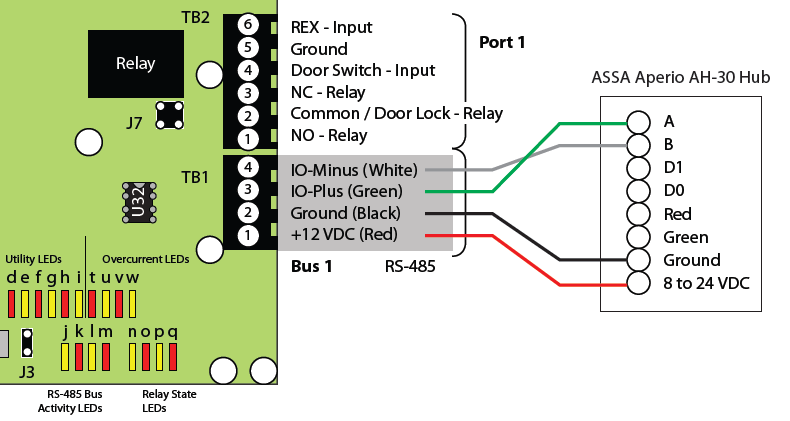
Connecting the hub to the NXT Mercury Powered controller using the RS-485 interface is the default method. It is the same wiring for the AH-15 and the AH-30.
6.1 RS-485 Wiring to NXT Mercury Powered Controller
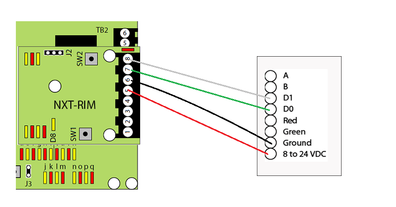
6.2 Wiegand Wiring to NXT Mercury Powered Controller
When connecting to the controller via Wiegand you must have a Reader Interface Module (RIM) plugged into the controller’s reader port and it needs to be configured for Wiegand (Refer to the RIM Installation guide for setup instructions. The hub is wired into the 8-pin terminal block connected to the RIM.
6.3 RS-485 Wiring to a Mercury Controller
- The AH30 Generation 5 hub is ONLY compatible with the MP series controllers.
- RS485 busses on EP and LP controllers are labelled TB2 and TB3. However some controllers only have a TB2 bus.
- RS485 busses on MP1502 and MP4502 controllers are labelled TB1500 and TB1501. However MP1501 controllers only have one RS-485 bus (labelled TB1301).
Mercury SPM (Intelligent Controller) | AH30 Hub |
TR+ | RS485 A |
TR- | RS485 B |
GND | GND |
8-24VDC | VIN (12-24VDC) |
6.3 Dip Switch Setting:
• Switch 10 - Antenna set to INT not EXT
6.4 Set Comm Address
- In Doors.NET > Hardware Settings click on the bus with the hub
- Note the comm number shown in the grid
- Set the comm dip switches on the hub to match the comm number in the grid (refer to the dip switch table at the bottom of the page)
- The comm address set on the hub must match the address shown in the software or else the hub will not come online.
7.0 Adding the AH30 Hub
7.1 Connecting the AH30 to an NXT-MSC Controller
- Click on Setup >> Hardware Setup >> All to display the hardware tree.
- Expand the controller you wish to use and highlight the controller’s bus.

- Expand the controller bus and you will see Inputs, Outputs and a reader.
- Select the reader, then click on the Hardware Browser tab near the top of the screen.
- Click on the Remove icon to remove the reader from the bus.
- Select the bus again and you will see the bus properties on the right.
- Change the bus protocol from Keri Systems to Mercury Security.
- Save the bus settings. You will then be prompted to reset the controller, so confirm to go ahead with the reset.
- With the bus still selected you can then click on the Add AH30 icon located on the hardware select ribbon bar.
- Click the ACCEPT button on the dialog box.
- The AH30 hub will then be added to the controller bus on the hardware tree.
- With the AH30 hub selected on the hardware tree, the hub properties will appear on the right. By default you will see that the hub's default address is 1. This address should match what is configured on the hub using the DIP switch. If you are adding additional AH30 hubs they will automatically be addressed 2, 3, 4, etc and the correct address must be configured accordingly using the DIP switch.
- If the AH-30 is addressed correctly the device should come online within a few seconds.
- When the hub is selected on the hardware tree you will then see the supported Aperio devices on the hardware select ribbon bar.
Note: If the Aperio icons are not available, please refer to License Manager permissions to ensure that your system is enabled for Aperio.

7.2 Connecting an AH30 Generation 1-4 Hub to a Mercury EP, LP or MP Series Controller
- Click on Setup >> Hardware Setup >> All - the hardware tree will be displayed.
- The Mercury SPM (MSC/SCP) gateway will be displayed at the top of the hardware tree. Existing controllers will be displayed beneath the gateway.
- Expand the EP, LP or MP controller that the AH30 is connected to.
- You will see the controller's RS485 busses (labelled TB2 or TB3) or if using MP series controllers they will be labelled TB1500 and TB1501.
Note: Some Mercury SPM (controllers) only have one RS485 communication port. - With the RS485 bus selected click on the Add AH30 icon from the hardware select ribbon bar.
- A dialog box will appear allowing you to adjust the quantity of hubs you wish to add. You can add up to 15 AH30 hubs per controller bus, subject to what is set on your Doors.NET license. The dialog box also allows you to change the default description.
- Click the ACCEPT button and the hub will be added to the controller's RS485 bus.
- Expand the bus and select the AH30 hub.
- When the hub is select you will see the hub's properties displayed on the right. You will see that the first hub added to the bus defaults to address #1. This must match what is set on the hub using the address DIP switch (see section 8.0).
- If the hub is wired correctly to the controller and addressed correctly it should be showing as online.
- Online events for the AH-30 will also be displayed in live events.
- When the hub is selected on the hardware tree you will then see the supported Aperio devices on the hardware select ribbon bar.
7.3 Adding a Generation 5 AH-30 Hub to a Mercury MP Series Controller
- Only the Mercury MP Series controllers support the Generation 5 AH-30 hubs.
- The Gen 5 AH-30 hubs use Aperio firmware, whereas previous AH-30 hubs used Mercury firmware. Therefore, before adding the Gen 5 AH-30 you must first change the protocol on the RS-384 bus to Aperio.
- Because the AH-30 hub uses Aperio firmware, once the bus protocol has been changed only Aperio Gen 5 AH-30 hubs can be added to that bus.
- In Doors.NET go to Setup >> Hardware Setup >> All.
- Expand the MP series controller which the Gen 5 AH-30 is connected to. The communication busses will be displayed.
Note: The MP1501 only has one RS-485 communication bus. - Select the bus that the Gen 5 AH-30 hub is added to.
- The bus properties will be displayed on the right.
- In the General settings, change Protocol (Serial) from Mercury Security to Aperio.
- Save the bus settings.
- You will now be prompted to memory reset the controller - confirm to go ahead with the controller reset.
- With the bus still selected click on the Add AH30 (Gen 5) icon from the hardware select ribbon bar.
- A dialog box will appear allowing you to change the default description and to adjust the quantity you wish to add.
- Click ACCEPT and the Gen 5 AH30 will be added to the hardware tree - you will need to expand the RS-485 bus to view the device.
- Select the Gen 5 AH30 and the device properties will be displayed on the right.
- In the General properties you will see that the comm address for the first device on the bus is address 1, the second is addressed number 2 and so on. Ensure that the device address in the properties matches the address which is configured on the hub's DIP switch.
- If the hub is addressed correctly and wired correctly into the controller bus it will come online within a few seconds.
8.0 Addressing the Hub
The address of the hub is determined by Doors.NET. Refer to the Comm Address field in the hub properties to determine the device address for the hub.

This addressing follows a specific pattern depending upon the types of hubs being installed. Refer to the table below appropriate to your installation.
| Bus Number | First Hub Address | Second Hub Address |
|---|---|---|
| 1 | 1 | 5 |
| 2 | 2 | 6 |
| 3 | 3 | 7 |
| 4 | 4 | 8 |
| Bus Number | 8-Port Hub | 1-Port Hub 1 | 1-Port Hub 2 | 1-Port Hub 3 | 1-Port Hub 4 | 1-Port Hub 5 | 1-Port Hub 6 | 1-Port Hub 7 | 1-Port Hub 8 |
|---|---|---|---|---|---|---|---|---|---|
| 1 | 5 | 9 | 13 | 17 | 18 | 19 | 20 | 21 | 22 |
| 2 | 6 | 10 | 14 | 17 | 18 | 19 | 20 | 21 | 22 |
| 3 | 7 | 11 | 15 | 17 | 18 | 19 | 20 | 21 | 22 |
| 4 | 8 | 12 | 16 | 17 | 18 | 19 | 20 | 21 | 22 |
| Bus Number | 8-Port Hub | 1-Port Hub 1 | 1-Port Hub 2 | 1-Port Hub 3 | 1-Port Hub 4 | 1-Port Hub 5 | 1-Port Hub 6 | 1-Port Hub 7 | 1-Port Hub 8 |
|---|---|---|---|---|---|---|---|---|---|
| 1 | 1 | 23 | 24 | 25 | 26 | 27 | 28 | 29 | 30 |
| 2 | 2 | 23 | 24 | 25 | 26 | 27 | 28 | 29 | 30 |
| 3 | 3 | 23 | 24 | 25 | 26 | 27 | 28 | 29 | 30 |
| 4 | 4 | 23 | 24 | 25 | 26 | 27 | 28 | 29 | 30 |
NOTE: Once the hub has been added to an NXT-MSC controller you MUST perform a RAM reset. The controller will re-configure the RS-485 protocol for Aperio devices. Only other Aperio devices can be used on that bus; no other peripheral type will be accepted.
Setting the Address on the Hub
There are 30 available address numbers for the hubs, set via the DIP switch on each hub. For example, Switch 1 in the UP position and all others DOWN will set the unit to address 1. All 30 address switch positions are shown in the figure below.

Related Articles
Aperio AH30 Hub Setup in Doors.NET
1.0 Introduction The following document explains how to setup the AH30 and the Generation 5 AH30 hub in Doors.NET. The document provides information regarding the setup process in Doors.NET, correctly configuring the RS-485 communication bus and ...Aperio AH-40 Hub Setup in Doors.NET
1.0 Introduction This quick start guide walks you through the process of setting up an Aperio AH-40 Hub to a Mercury LP or MP series controller in Doors.NET. Notes: The AH-40 hub is a network device and it is ONLY compatible with Mercury LP series ...