Basic Entraguard Controller Setup in Doors.NET
1.0 Introduction
Entraguard Doors.NET installation and controller configuration is a three step process. Each of these steps
has its own document, with controller configuration broken into separate documents per hardware type.
has its own document, with controller configuration broken into separate documents per hardware type.
• software installation – DoorsNET_Software_Installation.pdf
(p/n 01565-001)
• license manager and gateway configuration – License_Manager_and_Gateway_Configuration.pdf
(p/n: 01565-002)
(p/n: 01565-002)
• Entraguard controller configuration – Basic_Entraguard_Configuration_In_DoorsNET.pdf
(p/n: 01238-001)
(p/n: 01238-001)
This document covers the basic configuration of Entraguard controllers in Doors.NET software. It assumes Doors.NET has already been successfully installed on your host PC, the software license has been activated, and the PXL gateway has been configured.
Doors.NET supports Keri's Entraguard family of Telephone Entry Controllers (Silver, Titanium, and Platinum). These controllers can function as a single primary unit, multiple primary units, or as a node on a PXL500 network for seamless integration with other PXL500 controllers.
• These are the minimum firmware revisions for Entraguard products eligible for Legacy conversion:
- Titanium and Silver -
v7.6.09
- Platinum -
v9.1.09
• These are the minimum firmware revisions for Entraguard products eligible for Standard Entraguard licensing (subject to no conversion/legacy licensing fees):
- Titanium and Silver -
v7.8.01
- Platinum -
v9.2.01
This guide provides setup information for installing an Entraguard controller in Doors.NET. For wiring diagrams, technical specifications, installation recommendations and setup of communication methods please refer to the following existing Entraguard documentation:
• Entraguard Titanium Quick Start Guide - p/n - 01962-001
• Entraguard Silver Quick Start Guide - p/n - 01960-001
• Entraguard Platinum Quick Start Guide - p/n - 01553-001
This setup guide uses an Entraguard Silver controller as an example, but the process for bringing any Entraguard unit online is identical for each Entraguard model. It assumes that the software has already been installed and that the PXL500 Gateway is setup using the Gateway Wizard.
2.0 Licensing Requirements
Your Doors.NET license must have PXL-500 and Entraguard hardware types enabled regardless of whether PXL-500s will exist in the system or not. The reason for this is because a primary Entraguard controller is initially manually added and comes online to the software as a PXL-500. An auto-configuration is then performed to correctly detect the exact Entraguard model.
To check the license is correct perform the following:
1. Open the License Manager (Start >> All Programs >> Doors .NET >> License Manager.
2. Click the License tab to display the system’s licensed components.
3. Scroll down the list until you locate the supported hardware section.
4. Verify that Entraguard and PXL-500 are both set to true.
3.0 Adding an Entraguard Primary Controller to the PXL Gateway
An Entraguard controller can operate as a primary or secondary controller on a PXL network. Communication to the primary controller can be via serial, Ethernet or modem.
Important Note: If you are upgrading your installation from Doors32 to Doors.NET and an Entraguard is the primary controller then you MUST perform a hard-reset on the primary controller.
1. Open the Doors.NET login window by clicking the client icon from the desktop.
2. Login to the software using the default username and password of admin / admin.
3. Once you are in the software click the Setup tab, then Hardware Setup.
4. Open up the hardware tree by clicking the All tab.
5. The PXL500 Gateway appears at the top of the hardware tree. Highlight the gateway and verify in the gateway properties that it is online.
6. While you have the PXL gateway highlighted, click the ‘Add Entraguard’ icon.
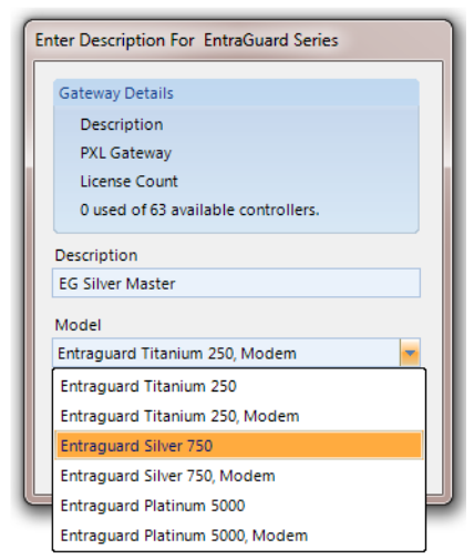
7. Enter a description for the new controller.
8. Select the exact Entraguard type from the Model drop-down list.
9. The primary Entraguard appears in the hardware tree beneath the PXL gateway.
4.0 Configure the Communications Channel
If your system is an upgrade from Doors32 and your previous system used sites mode you will notice that all controllers will have been copied across into the same PXL gateway. This is because Doors.NET supports multiple primary controllers (multiple sites) but the hardware tree still allows you to continue to maintain the sites mode style organization. Each primary requires its own communication channel, however, unlike Doors32, Doors.NET allows you to have multiple primary controllers communicating via different communication methods.
As previously mentioned, there are three different supported communication methods for PXL and Entraguard controllers, they are as follows:
• Serial connection (from the PC’s physical COM port, a recommended USB serial adapter, or a Keri USB Comm Module) – The J11 (INT Modem) jumper must be removed. The J19 and J20 jumpers should be shorted for a serial or USB serial adapter, but removed when using a Keri USB Comm Module.
• Modem connection – The J11 (INT modem) jumper must be shorted when communicating to the Entraguard’s internal modem. Jumpers J19 and J20 must be shorted when communicating to an External modem wired into the Entraguard’s TB12 serial port.
• Ethernet connection using a LAN module such as the LAN-520 – Remove jumpers from J11, J19, and J20 when using the plug-in LAN-520.
Note:
The Lan-520 Ethernet module and the Keri USB Comms Module can only be used on Entraguard board REV ‘PCB 23217-001’ or above. Earlier board revisions do not have the J7 port that these modules plug into.
Follow the instructions for the primary Entraguard according to the communication method you will be using.
5.0 Serial Connection
- Highlight the Communication Channels node in the hardware tree.
- Click the Serial Communications Channel icon.
- A channel named ‘New Channel’ appears in the hardware tree.
- Highlight the new channel so you can view its properties to the right.
- Double-click False and it will change to True which will enable the channel.
- Set the COM port number that corresponds to the serial device being used. If you are unsure what COM port to specify, go to Device Manager on the host PC and expand the node Ports – COM and LPT. If the device is correctly installed the assigned COM port number will show next to the device in parenthesis, i.e (COM3).
- Give the communication channel a descriptive name.
- Click save and the channel setting will be written to the database.
- Highlight the primary controller in the hardware tree.
- In the controller properties, locate Communication Settings >> Communication Channels and select from the dropdown list the new channel you have just added.
- Click the blue save icon at the top of the controller properties and within a few seconds transactions should appear in live events signifying that the primary controller is online.
6.0 Modem Connection
- Highlight the Communication Channels node in the hardware tree.
- Click the Modem Communication Channel icon.
- A channel named ‘New Channel’ appears in the hardware tree.
- Highlight the new channel so you can view its properties in the grid.
- Double-click False to set it to True.
- Set the COM port number that corresponds to the serial device being used. If you are unsure what com port is assigned to your external modem go to Device Manager on the host PC and expand the node Ports –Com & LPT. If the COM port is correctly installed and enabled the assigned COM port will displayed.
- Give the communication channel a name.
- Click save and the channel setting will be applied to the database.
- In the controller properties >> Communication Settings >> Communication Channel select the new channel from the drop-down list.
- Enter the phone number for the modem connected to the master Entraguard at the remote site.
- Within a few seconds the master controller should come online.
Note: Once connected, the modem line stays connected until manually disconnected. It is important to know this as for some phone systems this could result in a large phone bill. Right-click the master controller and disconnect after performing an update.
7.0 Ethernet Connection
The LAN-520 unit must already be programmed with a static IP address, gateway and subnet prior to adding the Network Communication Channel. For information about setting up the LAN-520 module please refer to the ‘Basic LAN-520 Installation Guide’ – P/N 01519-001.
- Highlight the Communications Channel node in the hardware tree.
- Click the Network Communication Channel icon.
- A channel named ‘New Channel’ appears in the hardware tree.
- Highlight the new channel so you can view its properties in the grid.
- Double-click False to change it to True.
- The default Controller and Network Timeout settings do not need to be adjusted.
- Give the communication channel a descriptive name.
- Click save and the channel setting will be saved to the database.
- Highlight the master Entraguard controller.
- In the controller properties locate Communication Settings >> Communication Channel then select from the dropdown list the channel you created.
- Selecting a Network channel will automatically display an IP address field, this is where you input the static IP address which is assigned to the LAN-520.
- The LAN-520 default port number is also automatically set at 10001.
- Click save after assigning the communication channel and specifying the IP address.
- Within a few seconds the controller should come online.
- The Live Events grid will also display transactions indicating the Entraguard primary controller is online. You will also notice that an initial update will automatically start and then complete.
|
|

P/N: 01277-001 Rev. A
|
Related Articles
Entraguard Autoconfiguration in Doors.NET
As well as detecting the primary controller type, all Entraguard secondary controllers (and PXL secondary controllers) are also detected and added to the system using auto-config. Converted databases will, of course, already have the controllers ...Adding and Editing Entraguard Users in Doors.NET
1.0 Introduction Each person to be granted access to secured areas using an Entraguard controller will need a User ID assigned to them. If a mixed PXL/Entraguard system is in use, each person may have assigned to them both a card and a User ID. 2.0 ...Entraguard Configuration and Settings
Configuring the EntraGuard Telephone Entry Controller The EntraGuard Controller properties can be viewed by going to Setup >> Hardware Setup >> All. Highlight the EntraGuard in the hardware tree (beneath the PXL gateway) and the controller properties ...Entraguard Troubleshooting Guide
1.0 Introduction The troubleshooting and diagnostics reference guide provides instructions to assist with tracking down the source of many basic controller installation problems. If there is a problem with a controller's installation, please review ...Entraguard Silver Data Sheet
Entraguard Silver Data Sheet (attached)