Basic Input/Output (I/O) Control
Basic Input/Output Control
1.0 Introduction
The feature allows you to link any available input to any available output, or group of outputs connected to the same controller (this includes outputs that exists on different NXT 4x4 or NXT GIOX modules - but must be connected to the same controller). Once the feature has been configured, the decision making is performed by the controller itself, meaning the controller does not have to be 'online' to the software for it to function.
Note: Basic I/O Linkage with PXL controllers requires an SB-593 satellite board which provides you with general purpose inputs and outputs.
2.0 Basic Link Action Setup
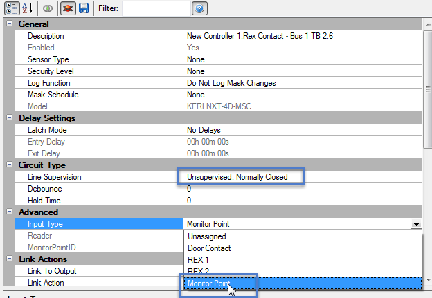
Link Actions can only be assigned to 'Monitor Points' which are essentially available inputs on the system. By default the NXT and MSC controller inputs are assigned as door contacts and primary RTE inputs. If neither of these functions are required on the controller you can highlight the controller inputs then un-assign the door functions by setting them to 'Monitor Points'.
2.1 Using the Controller's Inputs
- From the hardware tree, double click on an NXT or MSC controller so that the buses are displayed
- Double-click one of the buses then double-click on inputs
- If either the RTE 1 or door contact will not be used, highlight one of these
- Ensure Advanced View is enabled
- From the properties on the right locate 'Advanced'
- Change the input type to 'Monitor Point'
- From the Circuit Type setting you can set the input to be either 'normally-open' or 'normally-closed'

2.2 Using NXT 4x4 or GIOX Inputs
- Once you have added a 4x4 or a GIOX to one of the buses of the controller it will immediately appear beneath the bus in the hardware tree
- The inputs on these modules are automatically designated as 'Monitor Points'
- The outputs on these module are automatically setup as Control Points (which are effectively available outputs).
2.3 Using PXL inputs
- Double-click the PXL-2D in the hardware tree
- Double-click Inputs
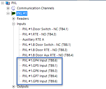
- If the satellite board is configured for 2 door control you will have 5 general purpose inputs at the bottom of the list.

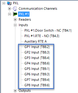
- If the satellite board is configured for I/O, then 8 of the inputs in the list will be available for basic IO linkage.

3.0 Link Action Setup
- Highlight an input/monitor point and locate 'Link Actions' in the properties
- From Link to Output select an available output you wish to activate when the selected input goes active.

- From the Link Action setting how you wish the output to respond to the input. It can either follow the state of the input, Latch ON, Latch OFF, or Pulse On/Pulse Off. If the Link Action is set to Pulse then the output will activate for the duration of its 'default pulse time' (which can be changed in the output properties).
- The Link Schedule option allows you to select a time schedule when the link action will be active. Outside of the selected schedule the link action will not function.

- Belongs to Group - When using standard NXT and PXL controllers there is an additional setting named 'Belongs to Group' - this setting will group the input with other inputs that have this designation set to Yes. This creates an AND condition so that the selected output will only activate when all inputs with the group set to Yes are in the active state.
Related Articles
Local Linkage - Program an Output to Follow an Input
1.0 Introduction A basic Local Linkage example is to program an output on the system to follow an input, so that when the input goes active the output automatically goes active. When the input goes inactive then the output also goes inactive. Prior ...Program an Output to Follow an Input
1.0 Introduction To program a Global Linkage action you must have the Global Linkage feature enabled in your license. This example uses a monitor point (input) to activate a control point (output relay). The input can be a monitored door a motion ...MR16IN - Input Control Module Setup
SCP-MR16IN-S3 (Input Control Module) Setup The Input Control Module (MR16IN-S3) processor provides sensor interface and output controls for security/ access control and other applications. The controller has 16 input channels for supervised contact ...Change Card Reader Mode from an Input
1.0 Introduction A basic Local Linkage example is to program an output on the system to follow an input, so that when the input goes active the output automatically goes active. When the input goes inactive then the output also goes inactive. Prior ...MR16-OUT - Output Control Module Setup
1.0 Introduction The multi-device MR16OUT interface panel is dedicated to point control and monitoring, providing 16 general-purpose outputs as Form C relay contacts. The MR16OUT also provides individually configurable parameters that can be set for ...
