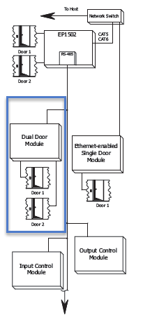
Dual Door Module (DDM) MR52 Setup
SCP MR52/DDM Setup
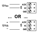
Power Supply to the MR52-S3
The MR52-S3 accepts either 12Vdc or 12Vac for power. Locate the power source as closed to the interface as possible. Make power connection with minimum of 18AWG wires. The input voltage is filtered and regulated to 5Vdc or 12Vdc.
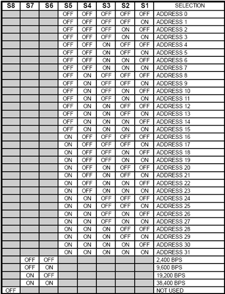
S1 DIP Switch Settings
- The SCP-MR52-S3 has a DIP switch (S1) - this is used to set the address of the module. Switches 1 to 5 select the device address. Switch 6 and 7 select the communication baud rate (the default baud rate for SCP hardware is 38,400). All other configuration settings are set via host software.
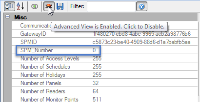
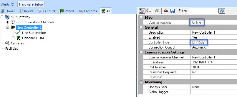
- The System Processor Module (i.e EP1502) is automatically assigned address 0 - You can see this if you enable Advanced View in the controller properties and look within the Miscellaneous section.
- If the SCP-MR52-S3 is the first module on the RS-485 network you would therefore set S1 to address #1.
- The SCP-MR52-S3 module communicates to an EP controller via the RS-485 communication link (TB6 connector) The interface allows for multi-drop communication on a bus of up to 4,000 feet (1,200 m).
The RS-485 interface can be set for either 2-wire or 4-wire configuration via the J3 jumper. By default J3 is set to 2-wire.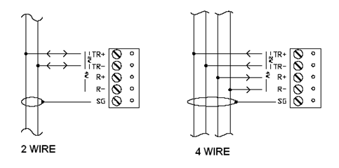
- To add an SCP-MR52-S3 to the system you must already have an EP controller added and online in the software.
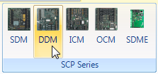
6. With the EP controller highlighted, click on the MR52-S3 icon in the ribbon bar.
7. A dialog box will appear stating the exact model (SCP-MR52) - you also have the option of adding multiple DDMs but it defaults to just 1.
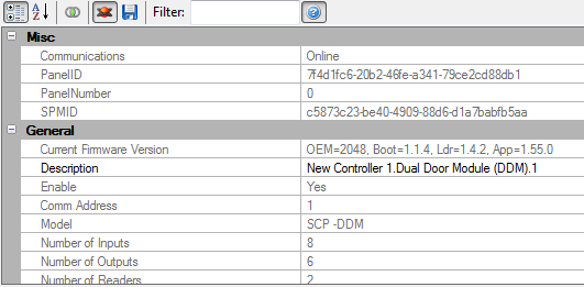
8. Click Accept and the MR52-S3 module will appear beneath the SPM in the hardware tree.
9. If the MR52-S3 is configured and wired correcting it should immediately come online.
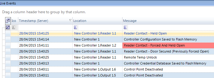
10. You should also see events for the MR52-S3 in the Live Events grid.
Related Articles
Single Door Module (SDM) MR51 Setup
Single Door Module (SCP-SDM) Setup in Doors.NET The SCP-SDM (Single Door Module) has all the I/O needed for controlling a single door. Each SDM will interface one card reader, two general purpose input monitor points and two control relays to provide ...NXT 4x4 Module Setup
Basic NXT 4x4 Setup and Configuration 1.0 Using Standard NXT Controllers The NXT 4x4 module is added to standard NXT controllers using Auto-configuration. The 4x4 module is connected to the controller via one of the available RS-485 ports (these are ...Doors.NET - Door/Reader Settings
1.0 Introduction The Setup Doors process allows you to configure door operating parameters, view event history, audit changes, view current status, manually lock/unlock, configure reader type (as applicable), and mask/unmask certain door event types. ...MR16IN - Input Control Module Setup
SCP-MR16IN-S3 (Input Control Module) Setup The Input Control Module (MR16IN-S3) processor provides sensor interface and output controls for security/ access control and other applications. The controller has 16 input channels for supervised contact ...MR16-OUT - Output Control Module Setup
1.0 Introduction The multi-device MR16OUT interface panel is dedicated to point control and monitoring, providing 16 general-purpose outputs as Form C relay contacts. The MR16OUT also provides individually configurable parameters that can be set for ...