EP1502/EP2500 Controller Setup Guide
1.0 Introduction
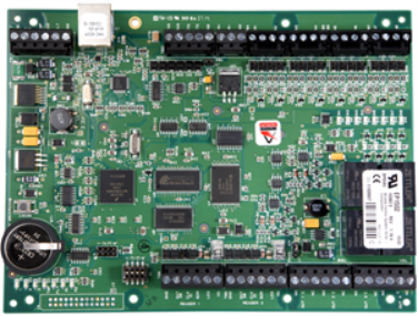
The EP4502 provide a two-door interface with auxiliary I/O, including onboard I/O for 2 readers, 8 supervised inputs and 4 relay outputs. In addition to centralized biometric template management, the controllers support a wide range of reader communication connections, including Wiegand, clock and data, RS-485 as well as all combinations of ID technologies such as magnetic stripe, proximity, smart cards, keypads, and LCD terminals.
This section explains how to setup and configure an EP1502/EP2500 Controller with the Doors.NET software. All EP controllers are pre-configured for use on a network, therefore additional TCP/IP configuration must take place in the field prior to placing each unit into service. The SPM (System Processor Module) is configured with the use of a web browser and network connection or cross-over cable. The following steps explain how to connect to the controller over a network and also how to re-configure the controller for a serial connection.
Notes:
- The following setup instructions assume that Doors.NET has already been installed and you already have the SCP gateway setup and online.
- This document covers configuration of the controller via the Doors.NET software. You can log into the controller via a web browser, and this will give you more settings to change, but you will need to be physically near the controller and you may be hindered by enhanced security settings in your browser.
- For extended and advanced controller settings please refer to the EP Controller Full Configuration document.
2.0 Factory Default Communication Parameters
- Network: static IP address: 192.168.0.251
Subnet Mask: 255.255.0.0
- Default Gateway: 192.168.0.1
DNS Server: 192.168.0.1
- Host port: IP server, no encryption, port 3001, communication address: 0
3.0 Factory Default DIP Switch Setting
You have to configure the S1 DIP switch to set the controller to its factory default settings.
| Switch | Definitions | |||
| 1 | 2 | 3 | 4 | |
| OFF | OFF | X | OFF | Normal operating mode. |
| ON | X | X | X | After initialization, enable default User Name (admin) and Password (password). The switch is read on the fly, no need to re-boot. See Special Features for more information on configuration options available with Switch 1. |
| OFF | ON | ON | OFF | Use factory default communication parameters.(Address: 192.168.0.251 Port: 3001) |
| ON | ON | X | OFF | Use OEM default communication parameters. Enable “Bulk Erase” Option. See the Hardware Installation Manual for more information on “Bulk Erase.” |
| X | X | ON | X | Disable TLS secure link. Switch is read only when logging on. |
- 1 – OFF 2 – ON 3 – ON 4 – OFF
4.0 Configure the Host IP Settings
- Go to Windows Control Panel.
- Select Network Sharing Centre.
- Click on Change Adapter Settings.
- Right-click the adapter for your Local Area Network and select properties.
- Select Internet Protocol Version 4 (TCP/IPv4).
- Click the PROPERTIES button.
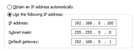
- Select 'Use the Following IP Address'.
- Configure the PC with the same settings as the controller's factory settings (except the IP address should be different).
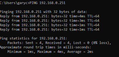
- Open a command prompt and verify that you can ping the controller's default IP address. Expect the IP address to reply successfully.
5.0 Add the Controller to Doors.NET
You can now add the controller to the Doors.NET software and then log into the controller's configuration to set it to a static IP address. This section assumes you have Doors.NET already installed and licensed and you have an SCP gateway setup and online.
- Log into the Doors.NET software.
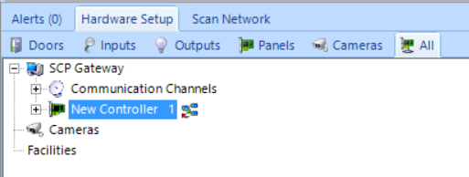
- Go to Setup >> Hardware Setup >> All to display the hardware tree.
- Select the SCP gateway (located at the top of the hardware tree).
- Click the SCAN NETWORK button.
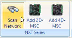
- The SCP gateway will scan the Local Area Network and will display any detected controllers, including the EP1502. It should also be displaying its default IP address.
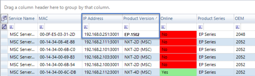
- Select the EP1502 and click on the IMPORT button.
- Click YES to proceed with the import then OK to confirm the import.
- Return to the hardware tree and you will see the controller now listed beneath the SCP gateway.
6.0 Set the Controller with a Static IP Address
You will now need to use 'Design Mode' to log into the controller's internal configuration and to set the controller with a static IP address. You can also log into the controller using a web browser, but this method via Doors.NET is the easiest method and avoids any browser security restrictions or limitations.
- Close the hardware setup page.
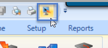
- Click the Design Mode icon.
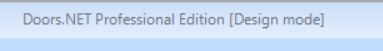
- When Design Mode is enabled it will state Design Mode in the title bar.
- Re-open the hardware setup page.
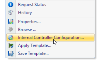
- Right-click the controller and select Internal Controller Configuration.
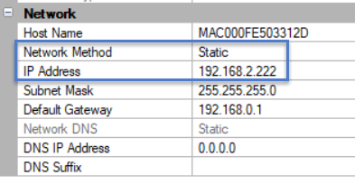
- From the web-page drop-down menu, select Network then click the refresh icon.
- The controller's IP settings will be displayed on the right.
- Set the network method to static.
- Enter the specific static IP address that you wish to assign to the controller.
- Save
 the controller's internal configuration.
 - Click the APPLY and REBOOT button.
- Click YES to confirm.
- Close the internal config window.
- The new static IP address will be assigned, the controller will reboot and the controller will then show as offline (because the host PC will now be on a different IP range).
- Now, go back to Windows Control Panel >> Local Area Network settings and set the host PC IP address to an IP address in the same range as the controller's new static IP address.
- Down-power the EP1502, set the S1 DIP switch the following: 1 - OFF 2 - OFF 3 - OFF 4 – OFF - this configures the controller for normal operation.
- Apply power to the controller, wait approximately 10 seconds for the controller to completely boot up, it should then be showing in Doors.NET as online.
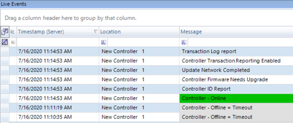
- Controller online events will be generated and displayed in live events.
- Exit the hardware setup screen and exit Design Mode.
7.0 Upgrade the Controller Firmware
If you see a 'Controller Firmware Needs Upgrading' event when the controller initially comes online then you will need to perform a firmware upgrade. The most up-to-date firmware file is included when you install the software.
- Select the new controller from the hardware tree.
- Click the firmware upgrade icon in the ribbon bar.
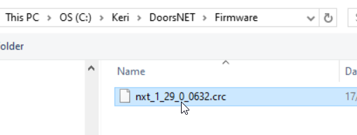
- The firmware upgrade directory will open and the most up-to-date firmware file will be displayed.
- Select the new firmware file and click OPEN.
- You will see a warning message that the controller will momentarily go offline during the upgrade. Confirm this message then click OK.
- The entire controller upgrade should be completed in approximately 60 seconds.
- When you see the Firmware Upgrade Complete message in live events, go to the controller status grid and the new firmware version will be displayed.
8.0 Enhanced Controller Authentication
If you connect to the controller for the first time via a web browser as opposed to via Doors.NET you will discover that there is an enhanced authentication requirement that prevents unauthorized access using the default user name and password. For this reason you must be near to the EP-4502.
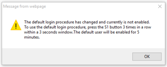
Before you can log into the controller using the default user name and password, you must:
- Transition S1 DIP switch 1 to the ON position (Do NOT cycle the power).
- You can then log in using the user name of admin and the password of password.
- Once logged in you should click on the Users link on the left.
- Add a new username and password then Apply the settings.
- Next time, if you login using the new log on credentials you will not need to adjust the S1 DIP switch.
Related Articles
EP4502 Controller Setup Guide
EP4502 Controller Setup 1.0 Introduction The setup for the EP-4502 controller is very much the same as the EP-1502 and EP-2500. All EP controllers are pre-configured for use on a network, therefore additional TCP/IP configuration must take place in ...EP1501 Controller Setup Guide
1.0 Introduction The EP1501 is an edge-capable intelligent controller that is expandable up to 8 downstream serial input/output modules and up to 16 MR62e network ready door controllers (for a total of 17 doors/openings). The feature-rich EP1501 ...LP4502- (S3) Controller Setup Guide
1.0 Introduction The setup for the LP4502 controller is very similar to the LP1502 and the LP2500. All LP controllers are pre-configured for use on a network, therefore additional TCP/IP configuration must take place in the field prior to placing ...Mercury EP-Series - Full Setup and Configuration Guide
1.0 Introduction This section explains how to setup and configure all controller settings and advanced options. All these settings can be found either by logging into the controller via a web browser or by accessing the controller's 'internal ...LP1502- (S3) Controller Setup Guide
1.0 Introduction The LP1502 controller is Mercury's next-generation advanced access control platform. They have direct hardware support for 2 openings and can scale to 64 access points. The LP4502 provide a two-door interface with auxiliary I/O, ...