Input/Output (I/O) Control - Using PXL-500 Controllers
1.0 Introduction
Using Doors.NET v3.5.1.21 and higher, you can apply basic I/O linkage actions to a PXL-500 controller which has an SB-593 satellite board connected to it. The SB-593 provides a PXL-500 with an additional 8 general purpose inputs and 4 general purpose outputs. Two of the inputs can be configured to manage a second door, making the PXL-500 a cost effective two door controller, while still providing an additional 6 inputs and 2 outputs.
This setup example will assume that a second door is being managed by the satellite board (inputs 1 and 2 are the REX/RTE input and the door sense input and outputs 1 and 2 are the second door lock output and the second door alarm output).
2.0 Setup Example (Output to Follow Input)
This example explains how to use input #4 on the satellite board to activate output #3 so that the output follows the state of the input. A typical application for this might be for monitoring a fire door which does not have access control. If the door is opened you can sound an alarm locally at the door using the associated output. When the door closes the alarm will stop sounding.
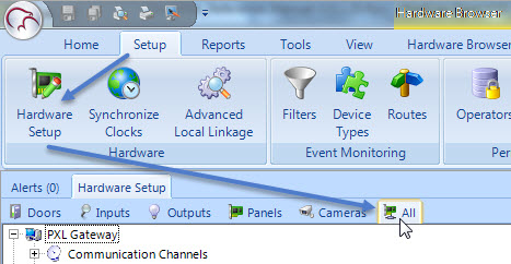
- From within Doors.NET, go to Setup >> Hardware Setup >> All to display the hardware tree.
- Double-click the PXL controller which has the SB-593 connected to it.
- Double-click inputs. You will see a list of inputs.
- If the satellite board is configured for managing a second door then you will notice the first 6 inputs are pre-configured for door functions (door sense plus RTE1 and RTE 2 inputs)
- However the RTE 2 for door 2 can also be used as a general purpose input, such as in this example as you will see.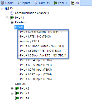
- Even if 2 doors are being controlled you will still have 6 available general purpose inputs (if you do not need an auxiliary RTE for door 2).
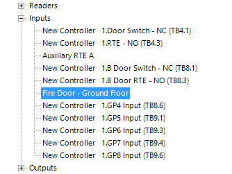
- Highlight the input and give it a descriptive name.
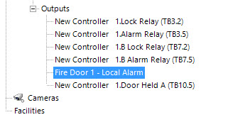
- Double-click outputs then rename output #3.
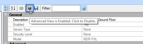
- Ensure Advanced View is enabled so you can see all the input's properties.
- Scroll down the input properties until you find Link Actions.
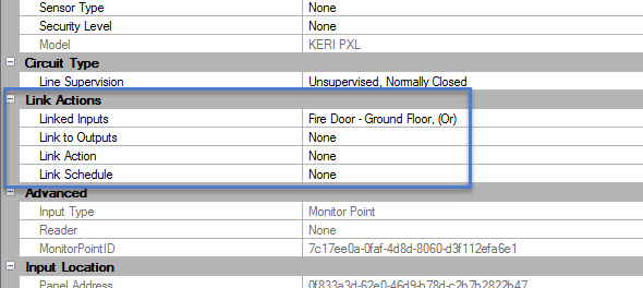
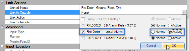
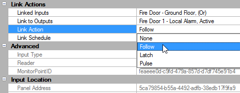
- Link to Output - Select the output #3 which you have renamed and set it to Active.
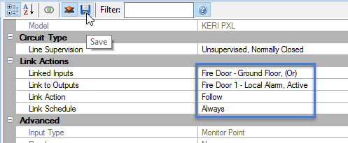
- Link Action - Set this to Follow.
- Link Schedule - Set to Always.
- Save the input settings
.
- Activate the input that is programmed with the link action.
- The linked output should activate and should deactivate when the input goes secure.
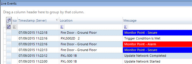
- At the same time these events should appear in the live events grid:
3.0 Link Action Options
Creating AND/OR Linkage Actions
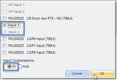
The basic I/O functionality on the PXL allows you to select additional inputs located on the same PXL to be included in the action.
- For example; you may only want to activate an output when there are 2 inputs BOTH in the active state.
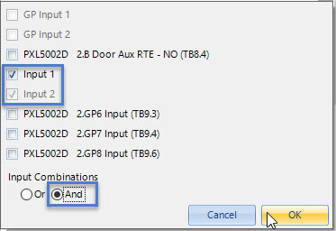
- Or you might want to activate an output when EITHER input goes active.
Link Actions
- Follow - The output follows the state of the input (when the input is active the output activates and when the input is inactive the output deactivates).
- Latch - The output latches on when the input is activated.
- Pulse - The output activates for the specified pulse time when the input is activated. When this option is selected you will see an additional setting that allows you to specify the pulse time.
Note: If you use one input to Latch an output ON you have to set the output to Active when you configure the link action. IF you use a different input to Latch the same output to OFF you have to configure the output to go to Normal.
Link Schedule
Determines when the link action can be activated. Always specifies that you will always be able to activate the link action.
Related Articles
Global Unlock - Using PXL-500 Controllers
This section explains how to enable the standard implementation of the Global Unlock feature using the dedicated Global Unlock input on the Primary PXL controller. The dedicated Global Unlock input is physically located between pins 5 and 6 of TB4 on ...PXL Elevator Control Using PXL or LC Controllers
1.0 Introduction PXL-500 controllers can be used for proximity elevator control applications. When using a PXL-500 with an SB-593 you will be provided with two floor increments of elevator control at an economical price. A single MS or Wiegand reader ...Global Lock, Lockout and Lockdown - Using PXL-500 Controllers
The global lock feature uses a dedicated input on the satellite board installed on the primary controller. This option will not appear if a satellite board is not installed. When the global lock input is triggered all online and functioning doors on ...PXL FAQs
PXL-500 Controller FAQs What reader types are supported with the PXL-500 controllers? The PXL-500P supports Keri MS series readers and the PXL-500W supports Wiegand readers. What method is used to communicate to a PXL-500 controller? The recommended ...PXL-500 Quick Start Guide
1.0 Introduction This quick start guide provides, basic installation information, drawings, first time power-on instructions, and short descriptions of key terms and concepts for installing controllers. These instructions apply to the PXL-500 ...