Intelliprox Blue - Wiring Diagrams
1.0 Controller Wiring Diagram
2.0 Fail-Safe Lock Wiring
A
fail-safe locking device requires power to keep a door secure. An
example of a fail-safe device is a maglock. If power is lost at the lock
the door will unlock. To power the lock via the controller's power
supply you should ensure that the lock draws a maximum of 1 amp,
otherwise the lock should have its own external power supply (separate
from the controller's power-supply).
Note: the
1.5KE39C transorb is provided with the Intelliprox Blue ship kit. It
should be installed as close as possible to the locking device to
prevent transients from the lock affecting controller operation.
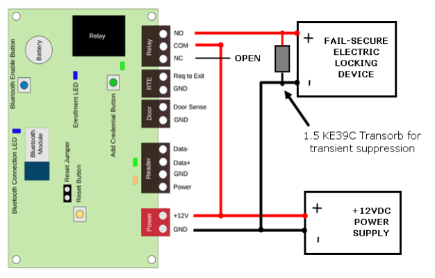
3.0 Fail-Secure Lock Wiring
A
fail-secure locking device requires power to unlock the door. If power
is lost at the lock the door will remain locked. To power the lock via
the controller's power supply you should ensure that the lock draws a
maximum of 1 amp, otherwise the lock should have its own external power
supply (separate from the controller's power-supply).
Note: the 1.5KE39C transorb is provided with the Intelliprox Blue ship kit. It should be installed as close as possible to the locking device to prevent transients from the lock affecting controller operation.