KE-1 Metal Enclosure Installation Guide
1.0 Introduction
A lock on the enclosure cover ensures that only authorized hands have access to the controller (two keys are provided). Ten knockouts are spaced around the body of the enclosure providing maximum flexibility for cable routing to the controller. The enclosure is mounted to any solid surface using four screws.
2.0 Dimensions
• 12.9" high x 10.4" wide x 3.1" deep

Figure 1: KE-1 Enclosure Dimensions
3.0 Enclosure Mounting
If this is not practical, Figure 2 is a layout drawing of the mounting hole locations.
Note: Figure 2 is not an actual size drawing and cannot be used as a drilling template.
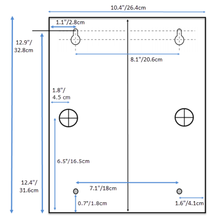
Figure 2: KE-1 Enclosure Mounting Holes
4.0 Cable Knockouts
Two are on the back of the enclosure. There are four on the top and four on the bottom of the enclosure.
Note: Figure 3a and 3b provides the measurements for the knockout locations. Figure 3 is not an actual size drawing and cannot be used as a drilling or routing template.
4.1 Top and Bottom of the Enclosure
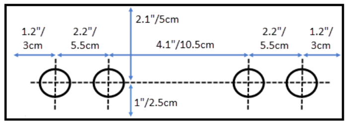
Figure 3a - Enclosure top knockouts
4.2 Back Side of the Enclosure
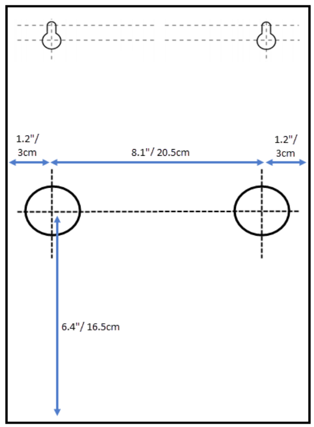
Figure 3b - Enclosure back knockouts
5.0 PXL Controller Mounting
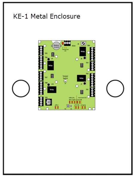
Figure 4: Mounting the controller into the enclosure
Once the enclosure is mounted and cabling is routed to the enclosure, the controller is mounted into the enclosure (see Figure 4). There are four standoffs in the back of the enclosure to which the controller is mounted. Use the four screws provided with the controller to mount the controller in the KE-1 Enclosure. Simply align the controller over the four standoffs and insert the screws.
Note: Do not over-tighten the mounting screws as this can damage the controller.
Related Articles
KE-8 Metal Enclosure Installation Guide
Section 1 – Specifications Section 2 – Wall Mounting the Enclosure Section 3 – Controller Installation Section 4 – Tamper Relay Board Mounting Section 5 – Wire Routing Section 6 – Keri Contact Information The KE-8 Controller Enclosure handles up to ...PXL-500 Hardware Installation Guide
1.0 Introduction This document contains installation guidelines and wiring diagrams for the installation of the PXL-500 Controller. Notes: A Serial connection is only supported when using the Doors.NET software. If using the PXL controller in ...SB-593 Hardware Installation Guide
1.0 Important Note: Keri Public Statement on the Amazon Key Keri Systems, Inc. has updated its policy regarding the integration of Amazon devices with Keri Systems controllers. We are pleased to inform you that Amazon has now provided official ...PXL-500 Controller Installation Guidelines
When Installing Controllers DO • If using modems for communication plan ahead to meet power and any telephone requirements for your system (1 phone line for the modem connected to the host computer and one for each master PXL-500/PXL-510 in each ...PXL-500 and Entraguard - Earth-Grounding Reference Guide
Introduction You should make a quality earth ground connection to all Keri PXL controllers to ensure the best possible operating conditions. An earth ground brings all electrically neutral lines to the earth's surface potential (essentially to a zero ...