LAN-520 - Quick Start Guide
1.0 Introduction
The following are basic setup instructions for the LAN-520 module. Some settings may not apply to every application.
Note: The LAN-520 AESP is an updated version of Keri’s LAN-520X device. If you are using the new NC-485X Network Converter with the LAN-520, you must use the LAN-520 AESP module (or the existing LAN-520X module). The original NC-485 Network Converter is NOT compatible with the new LAN-520 AESP (or the existing LAN-520X module).
Note: To set up the LAN-520, you MUST have technical knowledge of general networking in a PC environment. Please have a network administrator on site to resolve any special networking issues that might occur during device programming. Network topologies and strategies will vary.
As well as PXLs, LAN-520 modules also provide Ethernet connectivity to Entraguard controllers.
2.0 Installing the LAN-520 on the PXL-500 Controller
- Power-down the PXL-500 controller.
- On the Primary PXL-500 remove jumpers from JP6 and JP7 (highlighted).
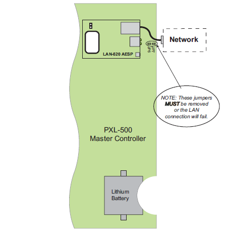
- Carefully insert the LAN-520 into TB13 with the RJ-45 connector to the right. Mounting screws are supplied to secure the LAN-520 to the PXL-500 controller. (The PXL500 will have to be removed from its enclosure to do this).
- Connect the RJ-45 port on the LAN-520 to the network or directly to the host PC via a cross-over network cable.
- Power up the PXL-500 (if it is a new controller a RAM reset is required).
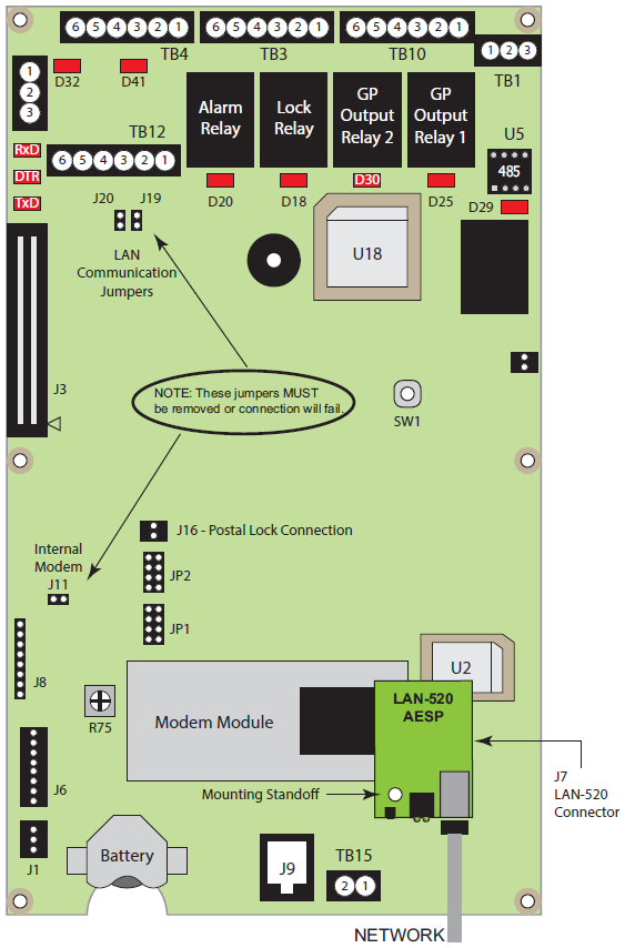
3.0 Installing the LAN-520 on an Entraguard Controller
Support for the LAN unit on Entraguard begin with PCB 23217-001 Rev. E. Earlier units cannot support a LAN unit.
- Power-down the Entraguard controller.
- On the Entraguard PCB, remove jumpers from J11, J19, and J20.
- Insert the LAN-520X into J7 on the Entraguard. Orient the LAN unit as shown in the image below.
Note: Mounting screws are supplied to secure the LAN-520 to the Entraguard unit. The Entraguard PCB will have to
be removed from its enclosure to do this.
- Connect the RJ-45 port on the LAN-520 to the network or directly to the host PC via a cross-over cable.
- Power up the Entraguard unit (if this is a new Entraguard panel, or a Primary controller from a Doors32 conversion then a RAM reset is required).
4.0 Factory Default DHCP Setting
The LAN-520 AESP module is DHCP enabled by default. When the LAN-520 AESP module is connected to a DHCP enabled router it automatically receives an IP address. The quickest way to find out what DHCP address has been assigned to the module is to install and run Lantronix Device Installer. Perform the following steps to install and use this program:
5.0 Download Lantronix Device Installer
- Register for an account by going to kerisys.com, click on Member Login, and fill out the registration form.
- You will receive an approval email to create your password.
- Once logged in to Kerisys.com click on Supporting Software.
- The following list of software applications will appear.
- Click on Lantronix Device Installer.
- Select Lantronix_Installer_4.4.0.7.zip.
- Click the DOWNLOAD button.
- Device Installer application will be downloaded to the host PC.
- You can now install Lantronix Device Installer.
6.0 Installing Lantronix Device Installer
- Locate the Device Installer zip file (typically it will be located in the Downloads folder of the host PC. Right-click the zip file and extract the contents to the Downloads directory.
- Double-click the setup executable file.
- The installer will initialize.
- You may see a notification window informing you that .NET Framework and Device installer are both required. Otherwise the installer will show that Device Installer will be installed.
- Click 'Install' to proceed with the installation.
- You will not need an active internet connection as all the required components are included in the executable file.
- Select the check box to confirm you have read the Microsoft Terms and Agreements.
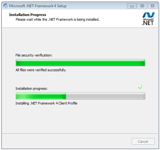
- If required, click install and the .NET Framework 4 Client Profile will install.
- Click Finish once installation is complete.
- The Lantronix Device Installer Setup Wizard will then start automatically.
- Click Next on the Welcome page.
- The Installation Folder page displays the default location where the program will be installed. You can click Browse to locate and select a different location.
- Click Next, then Next again to start installing Device Installer. Installation of this program should take no longer than a minute.
- Once installation is complete you can search for the application via the Windows search field.
- Right-click the Device Installer application file and select PIN to Taskbar so it will be easily accessible.
7.0 Running Lantronix Device Installer
- The Device Installer icon may also be located on the desktop so double-click this to open up the application.
- When you first open the program you may see a notification that no serial port has been detected, this is not of any concern so select ‘Do not prompt me about this’. Then click OK.
- Click No to the prompt asking if you want to check for updates.
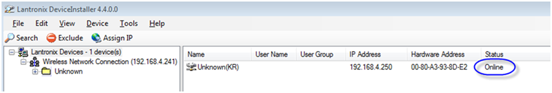
- If the LAN-520 AESP module has been connected to a DHCP router which is on the same physical subnet as the host PC then the device should appear. It should also show as online. The software automatically searches for the device via its MAC address.
- The device should display along with its assigned IP address. The MAC address will begin 00-80 if it is a LAN-520 AESP.
- Even if the address assigned by DHCP is an acceptable IP address it is still a dynamic address and therefore can still change. We therefore recommend assigning the IP which will make the assigned address static.
8.0 Assigning a Static IP Address
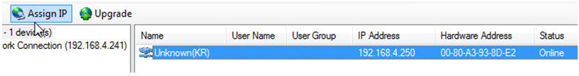
- Highlight the LAN-520 entry and click the Assign IP button.
- The Assignment Method page defaults to ‘Assign a specific IP address’ so click Next.
- Enter a new static IP address or leave as is (if you are happy with the address that was assigned by DHCP). On this page you can optionally add a gateway IP address as well. A gateway address is not required if the PC running Doors32/Doors.NET is on the same subnet. Click Next again.
- Click the Assign button to complete the static IP address assignment.
- Click Finish when you see assignment has successfully completed.
9.0 Telnet Session to Verify Communication
This will test the default port used by Doors32/Doors.NET to communicate to the device.
The telnet command is preferred over the ping command in testing communications because the telnet command will give a specific response from the device, whereas the ping command may give a response from a different device (if there is a duplicate IP address on the network).
- In a command prompt window type in, telnet [IP address] 10001 then enter.
- If successful a blank screen and a blinking cursor will appear. The link LED (bottom green LED) will blink on and off on the LAN-520 AESP indicating that port 10001 is open. Close the command prompt window and the link LED should stop blinking.
- If telnet is unable to connect, then review the settings. If the settings are correct then contact a network administrator to verify the needed ports are available. Some operating systems and hardware, such as routers and firewalls are set to block ports. Ensure these firewalls have ports 10001, 10021, and 9999, open for communication with the Doors32 or Doors.NET software.
10.0 Enable Telnet Client in Windows
If you try to make a telnet connection to the LAN-520 but you see the following message: ‘telnet is not recognized as an internal or external command, operable program or batch file’ then it is likely you are using Windows 10. Telnet Client is disabled by default on certain Windows operating systems.
Perform the following steps to enable Telnet in Windows 10:
- From the Windows start menu go to Control Panel >> Programs and Features.
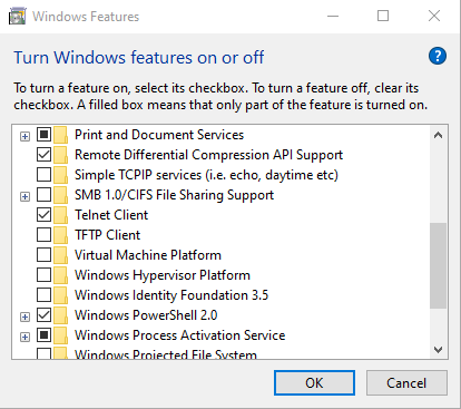
- On the left of the program list click Turn Windows Features on or off.
- From the Windows features list locate Telnet Client.
- Place a checkmark against Telnet Client.
11.0 Calculate Netmask: Number of Bits for Host Part
During the configuration of the LAN-520 AESP's TCP/IP address it will be necessary to add the subnet mask in number of host bits. The following is one way of calculating the host bits in a subnet.
A Decimal to Binary conversion of 255 will be all 1’s (11111111) and a 0 will equal 8 0’s (00000000).
If there are two 0’s in the subnet (255.255.0.0) there will be 16 0’s thus the host part will be 16.
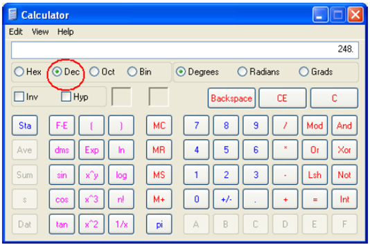
- To calculate a subnet like 255.255.255.248, open the Windows Calculator.
- Click on View > Scientific.
- Dec (Decimal) will already be selected.
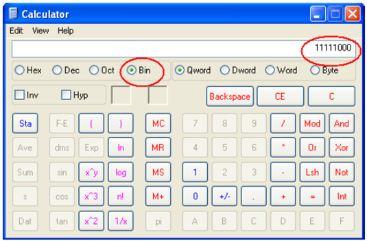
- Type in the last segment (248).
- Select Bin (Binary) and the binary conversion will take place.
- The 0s will represent the number of available bits. This number will be the Number of Bits for Host Part (248 =11111000 = 3). Number of Bits for Host Part is 3.
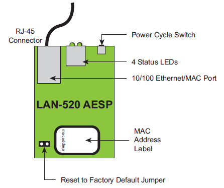
12.0 LAN-520 AESP Factory Reset Procedure
Perform the following steps to reset the LAN unit to its factory default settings:
- Power the unit OFF.
- Place a jumper across the Factory Default Jumper pins (located next to the MAC address label).
- Power the unit ON – this resets the LAN unit.
- Power the unit OFF.
- Remove the jumper from the Factory Default Jumper pins.
13.0 General Notes
- The new LAN-520 AESP unit start with the MAC address of 00-80
- We recommend setting a static IP address to the module using Device Installer. If the DHCP address changes then Doors32 or Doors.NET will no longer be able to connect to the LAN-520 AESP.
- The original NC-485 module is NOT compatible with the LAN-520 AESP or the LAN-520X. Only the NC-485X is compatible with these modules.
- To setup a LAN-520 AESP module you must have technical knowledge of general networking in a PC environment. Please have a network administrator on site to resolve any special networking issues that might be encountered during device setup and programming. Network topologies and strategies will vary.
- If the LAN-520 AESP is connected to a network that isn’t DHCP enabled the module will set itself to an IP address in the range of 169.254.XX.XX with a netmask of 255.255.0.0
- Keep in mind that although the Device Installer is capable of finding LAN520 devices on a local LAN even if they are on different subnets, routers and firewall settings can prevent the application from finding them.
- If you are able to telnet into port 9999 in the command prompt but not to 10001, it is very likely that the ports required by Doors32/Doors.NET are blocked and will require that a Network Administrator address the issue so a successful telnet session to port 10001 may take place.
- To use the LAN-520 AESP the PXL firmware must be at v8.4.43 (or greater).
Related Articles
LAN-520-AESP - Quick Start Guide
1.0 Introduction The following are basic setup instructions for the LAN-520-AESP module. Some settings may not apply to every application. Note: The LAN-520 AESP is an updated version of Keri’s LAN-520X device. If you are using the new NC-485X ...LAN-520 and NC-485 Network Converter Setup Guide
1.0 Introduction The NC-485X offers you more flexibility in managing multiple, remote, physical sites and enhanced networking capability. By using the LAN-520X in combination with an NC-485X Network Converter, PXL-500 controllers, which are normally ...LAN-520 - Enhanced Security Settings
1.0 Introduction If the LAN-520 channel 1 port # has been changed to 1234 then this is highly indicative that the device has been hacked. The default value for the port number is 10001. This is the number that identifies the channel for remote ...LAN-520 AESP - Full Installation Guide
1.0 Introduction The following are basic setup steps for the LAN-520 AESP. Some settings may not apply to every application. The following setup instructions explain how to use Lantronix Device Installer to find the DHCP assigned IP address and then ...LAN-520 Data Sheet
LAN-520 Ethernet Connectivity Data Sheet (attached)