Neutron Full Reference Guide
1.0 Introduction
As well as NXT credentials, the controller also supports many HID 125 KHz credentials.
Neutron controller installation and configuration is a three step process. Each of these steps has its own document, with controller configuration broken into a separate document.
- software - Doors.NET Software Installation pdf (P/N: 01565-001). Even though you will be using Visual Doors, you must first install Doors.NET (this will also automatically install Visual Doors software)
- license manager and gateway configuration pdf (P/N: 01565-002)
- controller configuration pdf (P/N: 02365-001- this document).
Notes:
- Neutron integration requires you to install Doors.NET v4.3.5.0 or later.
- The Neutron hardware type cannot co-exist with other hardware types. When Neutron is enabled on your license only Neutron controllers can be used on the system.
- Neutron can only be configured and managed using the Visual Doors software. Neutron hardware cannot be used with the Doors.NET admin client.
The controller inputs are fixed to being REX (request-to-exit) and DPS (door position switch). There is no secondary request-to-exit and there is no support for 4x4 or GIOX modules.
The controllers are flash upgradeable and the most current firmware version is made available within Visual Doors.
Connection to the controller network is via USB-RS-485 adapter which is wired into any one of the Neutron controllers. Communication to additional controllers is via a hard-wired RS-485 network (see section 8).
The Neutron controller is designed to provide full timed access functionality and event buffering even if the Appliance/PC is offline.
2.0 System Features and Capacities
Maximum Number of Controllers | 8 per appliance/PC |
Maximum number of readers | 16 per appliance/PC (8 x NXT Entry and 8 x NXT Exit readers) |
Maximum number of credentials | 1000 |
Maximum number of access groups per cardholder | 8 |
Maximum number of time intervals per day | 12 |
Maximum number of time intervals per time schedule | 50 |
Network connection | RS-485 - Up to 8 controllers per network |
Supported reader types | NXT reader and NXT Exit readers |
Supported credential types | Standard NXT and HID 125 KHz credentials |
Event buffer | 4,000 events held in controller buffer |
Software requirements | Keri Visual Doors (v4.3.0.5 or later) - on Windows 8,10 and Server 2012 and 2016 |
Offline configuration | Cardholder identity, credentials, access groups, time schedules, holidays, I/O configuration |
Firmware requirements | Compatible with firmware v01.00.15 or later |
Licensing requirements | Neutron must be enabled in the Doors.NET license |
3.0 Licensing Requirements
To use the Neutron controllers you will need a license key with the Neutron hardware type enabled. The license key with Neutron enabled will automatically be configured to support up to 8 controllers. You can either contact Keri Systems sales for a license key or you can generate your own key at the following URL: license.kerisys.com.
3.1 Verify Neutron is Enabled on Your License
This section assumes you have already successfully installed the Doors.NET software and have activated your license:
Note: The Neutron hardware type cannot co-exist with other hardware types. When Neutron is enabled on your license only Neutron controllers can be used on the system.
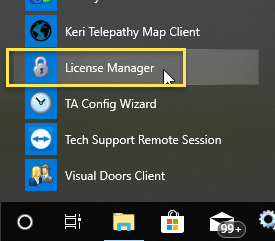
- From Windows Start menu go to Doors.NET >> License Manager.
- When the License Manager window opens, select Application Server.
- Click the License tab on the right pane.
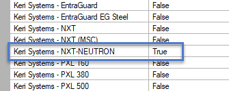
- Locate the Capacities section and verify that NXT-NEUTRON is set to 8 controllers.
- Scroll down to the Supported Hardware section and verify that NXT-NEUTRON is set to True.
- If Neutron is enabled you will be able to add the Neutron gateway.
4.0 Cable Recommendations
- Input Power - Belden 8461 - two conductor, stranded, AWG 18 wire
- NXT Readers - Belden 8723 (or equivalent) - this is a 2-pair shielded, stranded, twisted cable.
- RS-485 Network Cable - Belden 9501 - two conductor, shielded, twisted pair, stranded, AWG 24 wire or larger (note that increasing the wire gauge does not increase the total network length...
- The total network length is 4,000 feet/1,000 metres. - Input and Output Connections - Belden 8461 - two conductor, stranded, AWG 18 wire.
Note: The Lock Output relay may require a heavier gauge of wire depending upon the current demands of the lock and the length of the lock wiring run. - USB Adapter to PC Extension Cable - A USB extension cable can be used to extend the connection between the PC and the USB adapter - this cable should be a maximum length of 20 feet.
5.0 Wiring Diagrams
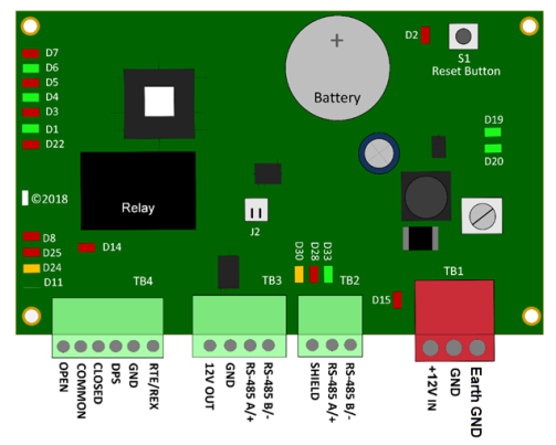
5.1 Controller Wiring Diagram
5.2 Lock Wiring Diagrams
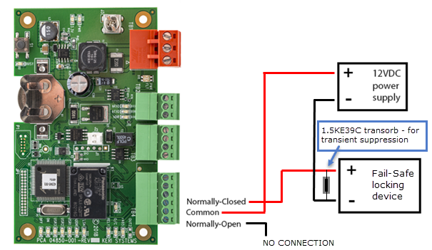
Fail-Safe Lock Wiring
A fail-safe lock requires power to keep the door locked. So if power should fail at the lock, the door will unlock - allowing quick entry or egress. A typical fail-safe lock is a magnetic lock.
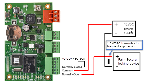
Fail-Secure Lock Wiring
A fail-secure lock requires power to unlock the door. If power fails at the lock, the lock will automatically lock and will not allow entry or egress. A fail secure door ensures a secured area remains secure regardless of the situation.
Notes:
- Transorbs are provided with the controller ship kit. They are used to protect the controller from voltage spikes induced on the port wiring. Keri strongly recommends wiring in the transorbs provided as close as possible to the lock.
- The Transorbs that Keri provides are non-polar; they can be installed in either orientation.
Isolation Relays
For locking devices that may induce heavy voltage spikes – Mag Locks and devices with heavy-duty solenoids such as turnstiles, vehicle gates, and overhead doors – Keri recommends using isolation relays. Keri has an Isolation Relay Kit (p/n IRP-1). Please refer to the IRP-1 Isolation Relay Installation Guide (p/n 01833-001) for detailed information.
6.0 LED and Jumper Definitions
(See Neutron controller diagram for location of the LEDs and jumper)
- J2 (TAMPER): Provides a normally-closed tamper input to the controller.
- D15 (PWR FLT): Indicates a short on the controller or if the power lines are reversed.
- D20 (PWR): Solid green indicates when the controller is powered-up.
- D19 (3.3V): Solid green indicates the output of the controller's onboard DC converter.
- D14 (TAMP): Solid red to indicate when the controller tamper input is active.
- D2 (BUSY): Solid red when the controller is being reset or during firmware upgrade.
- D24 (RS485): Quickly flashing amber RS-485 reader communication).
- D25 (O/C): Solid red to indicate if there is over-current on the controller's reader port.
- D22 (FLSH): Solid red to indicate when the flash memory chip is active.
- D8 (RELY): Solid red to indicate when the controller strike relay is active.
- D1 (ADDR): Controller address number (i.e blinks 3 times for address #3).
- D6 (ON): Solid green to indicate the controller is online.
- D7 (OFF): Solid red to indicate the controller is offline.
7.0 Controller Installation Guidelines
- Mount controllers in environmentally suitable areas - they require protection from temperature and humidity extremes.
- Ensure each Neutron controller is receiving between 12 and 14VDC - longer power lines cause a drop in voltage at the end of the run.
- Connect all Neutron controllers to a quality earth-ground.
- Connect the RS-485 shield wire to the GND connection of the USB-RS-485 adapter. Do NOT connect the shield wire to the frame ground of any of the controllers is this may cause a ground loop.
- Use the enclosure as a mounting template to mark drilling holes for permanent mounting.
- Route all controllers on the RS-485 network in a single, continuous daisy-chain. NOT in a star or a ring configuration.
- Add transient suppression across electric devices attached to the controller output. A transorb is supplied with the controller and it should be installed as close as possible to the locking device.
- Use an isolation relay (P/N IRP-1, or equivalent) if connecting to a parking gate, a turnstile, or any application that uses a large electric motor.
- The industry standard maximum RS-485 network length is 4,000ft/1000m.
- The RS-485 recommended cable type is Belden 9501 (or equivalent) - two conductor, shielded, stranded, twisted pair. Recommended wire gauge is AWG22.
- NXT reader extension cable type is Belden 8723 (or equivalent) - four conductor, shielded, stranded and twisted RS-485 wires. Recommended wire gauge is AWG-22.
8.0 Neutron Controller Connection
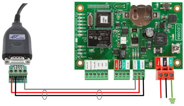
- Connect the USB end of the cable into an available USB port on the host PC.
- The adapter should be installed automatically and you should be able to find it in Windows Device Manager.
- Hard-wire a connection between RS-485+ of the adapter to TB2-RS-485 A+ of the first controller.
- Hard-wire a connection between RS-485- of the adapter to TB2-RS485 B- of the first controller.
- Connect the RS-485 shield-drain to the GDN connection of the USB adapter.
- The RS-485 +, RS-485 - and shield drain are daisy-chained to all other Neutron controllers on the network.
Notes:
- Every system requires a USB-RS485 adapter. The adapter, once installed will automatically be assigned a COM port and auto-configuration scans for controllers via this COM port.
- The adapter's assigned COM port number can be viewed in Windows Device Manager (Control Panel >> Device Manager).
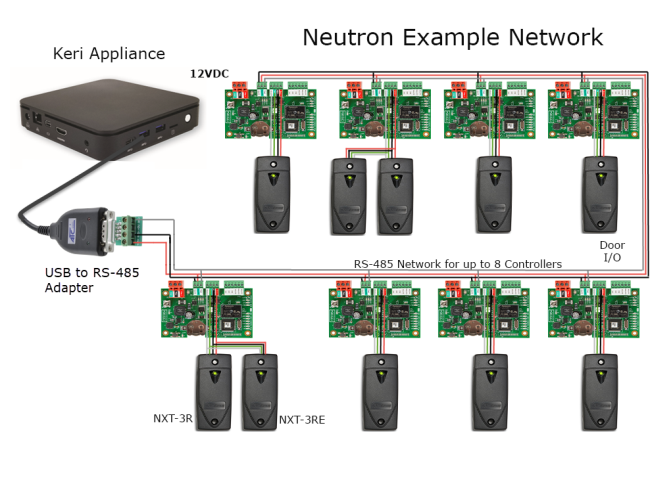
9.0 Neutron Controller Network Schematic
10. Controller Factory Reset
Before adding the controller to the Visual Doors software, you should factory reset the controller. The factory reset will clear all configuration and event history (but will, of course, retain the controller's MAC address) - so it can be found again via Auto-config.
- Down-power the controller.
- Hold down the S1 button while applying power.
- Continue to hold down the S1 button...
- Release the S1 button when the BUSY LED (D2) stops blinking.
- The FLASH LED (D22) will be solid red for aproximately 30 seconds.
- The FLASH LED (D22) will go off and the offline LED (D7) will then be solid red.
- The controller is now reset and ready for setup.
Note: If you release the S1 button too soon, or too late then no reset will occur.
11.0 Setup the Neutron Gateway
The Neutron gateway provides the communication link between Visual Doors and the Neutron network.
Note: If you have not yet activated your license key: following Doors.NET installation, you will be prompted to run the License Manager and before the License Manager opens you will be prompted to enter your license key... The License Manager is used to create the gateway.
- When the License Manager window opens, refer to the list of installed clients and services on the left.
- You will see the Neutron gateway listed but it will state: 'Licensed Needs Configuration'.
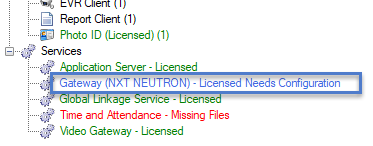
- Select the gateway from the list then click the SETTINGS button.
- Enter a name for the new Neutron gateway >> click OK.
- You will be prompted to start the gateway service.
- Once started, the gateway will be setup and ready to use.
12.0 Add a Neutron Controller in Visual Doors
The following steps explain how to connect to the Neutron network with the Visual Doors software.
- From the desktop, click the Visual Doors Client icon.
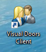
Note: You can also navigate to the Visual Doors Client location:
(C:\Keri\DoorsNET\Visual Doors.exe). - Log into Visual Doors with the default user name and password (they are both admin).
- From the home screen, click on the Hardware icon.
- When the Hardware screen opens click on the green 'Auto-Config' icon.
- Visual Doors will then scan all available COM ports on the PC and will detect the Neutron controllers on the network (via the USB-RS-485 network adapter).
- Once detected, the D33, D28 and D30 LEDs on the controller(s) should start blinking.
- On the Auto Config results window, click the APPLY button.
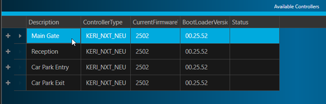
- Within a few seconds the controller(s) will be added to the hardware list and you will see an Auto-Config Complete message.
Close the auto config window. You will see the controllers displayed on the hardware screen. A green status icon to the left of the controller indicates that the controller is online.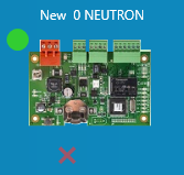
- The controller is now added and ready for further configuration.
- The red and green LEDs on the USB adapter will also be constantly flickering.
13.0 Firmware Upgrading
13.1 Controller Firmware Upgrade
If a controller requires a firmware upgrade you will see a notification in the live events grid. The event will display which firmware version is required.
- Go to the Hardware screen and select the controller that needs to be upgraded.
- On the right side you will see the controller properties.
- Click on the UPGRADE FIRMWARE icon.
- Select the controller from the list.
- In the top left corner of the firmware upgrade screen, select the required firmware bootloader file.
- Click the APPLY button.
- A progress bar will indicate when the bootloader upgrade is completed.
- Once complete, you will see a Firmware Update Succeeded message.
- With the controller still selected, next select the required controller firmware file.
- Click the APPLY button to also upgrade the controller firmware.
Notes:
- You should not attempt to upgrade a controller while a firmware upgrade is in progress. The correct procedure for updating multiple controllers, is to select all controllers first and then select the new firmware file and click APPLY.
- When you perform the firmware upgrade you will notice the progress bar reach 40% very quickly and then pauses. The remainder of the upgrade is slower and this is expected. It should take no longer than 2 minutes to upgrade the bootloader or the controller firmware.
13.2 NXT Reader Firmware Upgrade
When using Neutron controllers in Visual Doors, it is also possible to upgrade NXT reader firmware (providing the reader is programmed with firmware v04.00.00 or later). If you upgrade the reader to the most current firmware version (v04.00.03) it will be configured to read standard NXT credentials and 125KHz HID credentials.
Here are the steps for upgrading NXT readers in Visual Doors (upgrading a reader from firmware v04.00.00 to v04.00.03):
- Go to the Hardware screen and select one of the listed controllers.
- Click the UPGRADE FIRMWARE button.
- Click the + symbol located to the left of any of the controllers you see listed.
- Select a reader which has the v04.00.00 firmware.
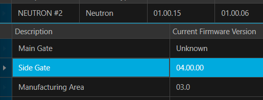
- From the Select Firmware File drop-down list, select the v04.00.03 firmware.
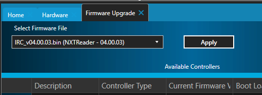
- Then click the APPLY button.
- The new firmware will be sent to the reader and the update percentage will be displayed in the status column.
- While the reader firmware is being updated the reader LED will blink green, amber and red.
- Once firmware upgrade is complete the reader will beep 5 times, the update percentage will show 100% and you will see an upgrade success notification.
- Confirm the notification and the new firmware version will then be displayed.
14.0 Basic Hardware Configuration
Controller and reader configuration is performed on the Hardware screen.
14.1 Controller Configuration
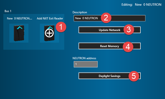
From the hardware setup screen, select a controller and the controller properties will appear on the right:
- Add NXT Exit Reader - Allows you to add an NXT Exit reader (or you can perform an auto-config to add an Exit reader).
- Description - Allows you to enter a new description for the controller.
- Update Network - Click the UPDATE NETWORK button to send a full update to the controller.
- Reset Memory - Click the RESET MEMORY button to perform a basic reset on the controller. This will clear the controller's configuration (including the cardholders) and the controller will go offline. You will need to perform an auto-config to get the controller back online again and then update the controller.
- Daylight Savings - Allows you to define specific daylights savings change date/time for the controller.
14.2 Reader Configuration
- Description - Allows you to enter a new description for the reader.
- Enabled - Toggles the reader between enabled and disabled.
- Manufacturer Model - You can select the specific model of NXT reader.
- Enable Door Contact - Enables door-forced and door-held functionality (when door contacts are installed).
- Held-Open Time - Allows you to adjust the door held-open time (when door contact is enabled).
- Enrollment Reader - Allows you to set the reader as an enrollment reader (for presentation enrollment).
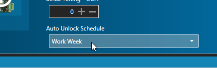
- Strike Timing - You can adjust the door unlock time/strike time.
- Auto Unlock Schedule - You can define an auto-unlock schedule which programs the door to unlock/relock at specific times of the day/week. The auto-unlock schedule needs to be created prior to assigning it in the reader properties. See section 15.0 below.
Notes:
- Inputs are door sense (normally-closed) and RTE (normally-open).
- Output is the strike for unlocking the door (alarm outputs and alarm shunt are not supported with Neutron).
Unlock time is the number of seconds to keep the strike activated, and if the door is closed sooner than that time, the strike activates when the door is closed.
15.0 Enrolling Cardholders
Visual Doors offers two methods of enrolling cardholders for use with the Neutron hardware. Credentials can be manually enrolled or presentation enrolled (using one of the readers on the system.
Note: when enrolling 26-bit HID credentials you will need to enter a facility code, whereas NXT credentials do not use a facility code.
15.1 Manual Enrollment
- From the Visual Doors home screen, click the Cardholders tile.
- When the Cardholders screen opens, click the green + (add) icon.
- Enter a first name and a last name for the new cardholder (the middle name is optional).
- Select the card format (NXT or Wiegand26).
- Enter the Imprint (this is the number printed on the card or fob).
- Set the status as Active.
- Set the new cardholder to Never Expire or you can enter an activation date and an expire date to make the card temporary.
- Assign an Access Group to the cardholder.
Note: the Neutron controller doors are NOT automatically added to the Total Access group - they will need to be manually added. - Click the ADD button to create the new card record.
- Click CLOSE to close down the add card window.
- The new cardholder will be automatically sent out to the controller network.
15.2 Presentation Enrollment
Presentation enrollment uses one of the readers on the system to detect the programmed card information.
- From the Visual Doors home screen, click the Hardware tile.
- On the hardware setup screen, select the reader and verify it is setup as an enrollment reader.
- Click on the Home tab, then click the Cardholders tile.
- Click the green + icon and a card record add window will appear.
- Enter a first name and a last name for the cardholder (middle name is optional).
- Set the status to Active.
- Set the new cardholder to Never Expire or you can enter an activation date and an expire date to make the card temporary.
- Set the card to Total Access or assign a different access group.
Note: the Neutron controller doors are NOT automatically added to the Total Access access group - they will need to be manually added. - Click the ADD button to create the new card record.
- Click CLOSE to close the add new cardholder window.
- The new cardholder record will now be selected in Visual Doors.
- In the Credentials section of the cardholder record, select 'Enroll From This Reader', then select, from the drop-down list, the reader you will be using for enrollment.
- Set the correct card format from the format drop-down list (Wiegand26 or Keri NXT).
- Present an card or fob to the reader. The reader will beep and you will see a momentary red pulse from the reader's LED.
- In Visual Doors the card number will appear in the Cardnumber field. If using 26-bit HID Wiegand cards a facility code will also appear.
- Click the Save / Add Card button to assign the credential to the cardholder.
- The new cardholder will be automatically sent out to the controller network.
16.0 Setup Time Schedules
Time Schedules are used in Visual Doors to determine what times cardholder will be able to gain access. Time schedules are used in access group setup but can also be used to automatically unlock and re-lock doors (time schedules can be assigned to doors as auto-unlock schedules). The following example will explain how to setup a time schedule that is active between the hours of 7:30 am and 6:30 pm (Monday to Friday):
Note: Visual Doors allows a maximum of 50 time intervals per time schedule.
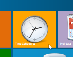
- From the Visual Doors home screen, click the Time Schedules tile.
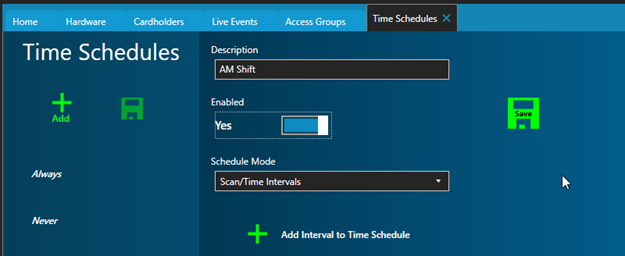
- Click the green + (add) icon on the left.
- Select the New Schedule entry.
- Enter a new description for the schedule (i.e Mon-Fri - Work Week).
- Click to enable the time schedule.
- Click the Add Interval icon.
- Select the days of the week you wish the interval to be active for.
- Click-on the clock icon next to the start time.
- On the large clock select the start time hour (7) and set AM.
- Then select the start time minutes (30).
- Next, click the clock icon next to the stop time.
- On the large clock select the stop time hour (6) and set PM.
- Then select the start time minutes (30).
- Click the green save icon.
- The time schedule is now setup and ready to use.
- You can also add additional time intervals to a time schedule (up to a maximum of 12 intervals per day).
17.0 Setup Access Groups
Access groups are a combination of time schedules and selected readers that determine when and where cardholders can gain access. Each door can be assigned a unique time schedule or multiple doors can be assigned the same time schedule.
The following example covers how to add a new access group and add a doors to that new access group.
From the home screen, click on the Access Groups tile.
Existing access groups will be listed on the left.
Click the Add icon.
Select New Access Group entry (at the bottom of the list).
Enter a description for the new group.
Beneath the access group description all the doors are listed, (along with their respective controllers).
Listed above the check boxes are all the available time schedules.
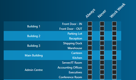
Place check marks in the doors (and their corresponding time schedules) for all the doors that will be part of this access group.
- Any doors that are not selected won't be part of the access group.
Once you have selected all the required doors the access group will be created, there is no need to save the access groups page.
- You will now be able to assign the access group to cardholders (see section 14).
18. Operate Doors
Visual Doors allows you to unlock, lock, lockout or lockdown any enabled doors on the system.
- From the Visual Doors home screen, click the Hardware tile.
- Select the door on the left that you wish to command from the software.
- Temp Unlock - The door will unlock for the duration of the strike time (the same amount of time the door will unlock if you present a valid card or from a Request-to-Exit). The door strike time can be adjusted in door setup (see section 13.2).
- Unlock - The door will unlock and will remain unlocked... unless manually locked, put into Lockout or Lockdown or overridden by the stop time of an auto-unlock schedule.
- Lock - The door will be locked and will remain locked... unless manually unlocked or overridden by the start time of an auto-unlock schedule.
- Lockout - (also referred to as Emergency Lockout) will immediately 'lockout' the door and prevent access from being granted with a valid card. Access will, however, still be allowed using request-to-exit buttons.
- Lockdown - (also referred to as Emergency Lockdown) will immediately 'lockdown' the door and prevent access from being granted with a valid card. Access will also not be possible using a request-to-exit button.
Note: If a door is disabled it will not appear on the Unlock Doors screen.
19.0 Auto-Unlock Schedules
Auto-unlock time schedules are used to automatically unlock and relock doors during certain times of the day. Refer to section 15 (Setup Time Schedules) to configure the times that you wish the door to unlock and relock.
- From the Visual Doors home screen, click the Hardware tile.
- Select the controller, then select the door that you wish to auto-unlock.
- The door properties will appear on the right.
- Locate the Auto-Unlock Schedule option at the bottom of the reader properties list.
- Select the appropriate time schedule.
- Save the door settings.
- The controller will be updated automatically.
20.0 Operators and Operator Permissions
The Operator Permissions screen allows you to very quickly and easily add additional system administrators and restricted users or to enable/disable the permissions of existing operators. You can configure an operator to only see certain tiles on the home screen. This example covers setting up an operator who will only be able to access cardholders, time schedules and access groups and run reports (but will not to be able to access the hardware setup or setup new operators).
From the home screen, click the Operators and Permissions tile.
- Select an account type from the list on the left, for example, Limited User.
Enter a User Name for the new user.
- Select an Account Type for the new user, such as Manager.
Enter a password for the new user account.
Re-enter the password for the new user account.
- Click the ADD OPERATOR button.
From the System Permissions list, deselect Hardware and Operators and Permissions.
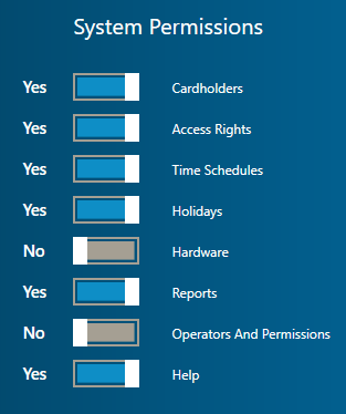
Click the SAVE button.
When you log into Visual Doors with the new account, the Hardware Setup, Doors and Operator Permissions tiles will be hidden from the home screen.
21.0 Running Reports
Visual Doors has a built-in report wizard and designer that allows you to create a new report from scratch or to modify an existing, saved report. The report wizard is very easy to use and you can save an unlimited number of reports so you don't have to enter your search criteria each time. Once reports have been saved they can also be exported to the hard drive, a network drive or removable media so you can share the reports with other people. Reports can be exported as PDF or Excel formats.
The following example explains how to run a report on all the system transactions for the past 2 days:
- From the home screen, click on the Reports tile.
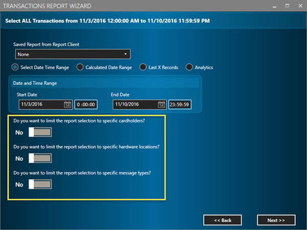
- The Reports Wizard window will appear.
- The default report selections are for all messages that have occurred for the current day since midnight. But as you can see, you have the option of running reports against specific cardholders, hardware or message type.
- To begin with, select Calculate Date Range.
- From the drop-down list, select Today - 2 Days.
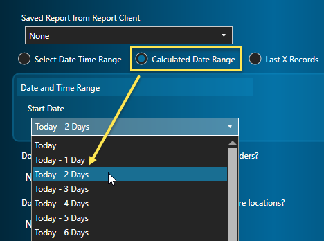
- Click NEXT.
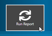
- On the next screen, click the RUN REPORT button.
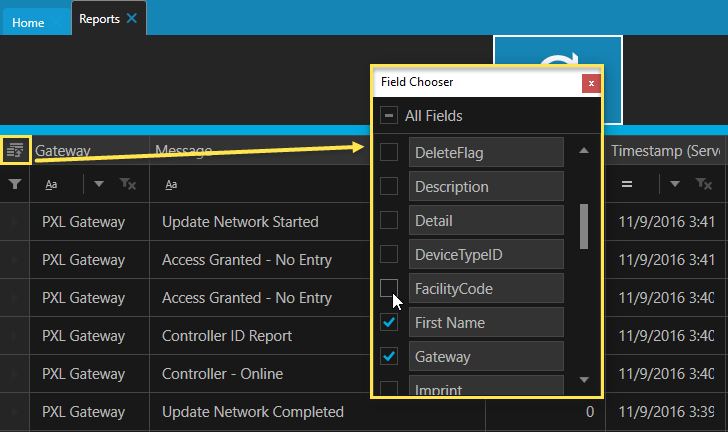
- The report information will appear on the grid behind the report wizard window.
- Minimize the report wizard to view the generated report.
- You can re-size and reposition any of the columns, plus as with Live Events, you can use the field chooser to select/deselect any of the columns.
The available report types are as follows:
•All Messages
•All Messages from Cardholder
•All Messages from Cardholder, MessageType
•All Messages from Control Point
•All Messages from Control Point, MessageType
•All Messages from Controller
•All Messages from Controller, Cardholder
•All Messages from Controller, Cardholder, MessageType
•All Messages from Controller, MessageType
•All Messages from Gateway
•All Messages from Gateway, Cardholder
•All Messages from Gateway, Cardholder, MessageType
•All Messages from Gateway, MessageType
•All Messages from MessageType
•All Messages from Monitor Point
•All Messages from Monitor Point, MessageType
•All Messages from Panel
•All Messages from Panel, MessageType
•All Messages from Reader
•All Messages from Reader, Cardholder
•All Messages from Reader, Cardholder, MessageType
•All Messages from Reader, MessageType
•All Messages from Search
•Last X Messages from Cardholder
•Last X Messages from Cardholder, MessageType
•Last X Messages from Control Point
•Last X Messages from Control Point, MessageType
•Last X Messages from Controller
•Last X Messages from Controller, Cardholder
•Last X Messages from Controller, Cardholder, MessageType
•Last X Messages from Controller, MessageType
•Last X Messages from Gateway
•Last X Messages from Gateway, Cardholder
•Last X Messages from Gateway, Cardholder, MessageType
•Last X Messages from MessageType
•Last X Messages from Monitor Point
•Last X Messages from Monitor Point, MessageType
•Last X Messages from Panel
•Last X Messages from Panel, MessageType
•Last X Messages from Reader
•Last X Messages from Reader, Cardholder
•Last X Messages from Reader, Cardholder, MessageType
•Last X Messages from Reader, MessageType
•Last X Messages from Search
22.0 Database Backup
The following steps explain how to perform a full database backup using the Doors.NET License Manager.
- From Windows Start Menu, go to Doors.NET >> License Manager.
- When the License Manager opens select Application Server from the list on the left.
- Click the SETTINGS button.
- Go to the Backup tab.
- Set the Time of Day (for when the backup will be performed) - for example: 5 minutes from the current time.
- Set the correct Day of the Week.
- Use the default file destination or change the path (for example to a removable drive).
- Click the SAVE button. You will be prompted to restart the Application Server, then wait for the backup to be created.
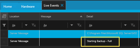
- Live events will indicate when the backup has started and completed.
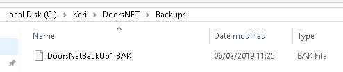
- Navigate to the destination directory and you will see the backup file.
Important Note: If you will be moving the database to a different PC both PCs must be running the same version of SQL - Or the new PC will need to be running a newer version of SQL. You will not be able to deploy an SQL database onto an older version of SQL (for example: you won't be able to use an SQL 2016 database on an SQL 2014 database engine - but you can run an SQL 2014 database on an SQL 2016 database engine.
Related Articles
Neutron Comms Cable Reference Guide
1.0 Introduction The USB-to-RS-485 communication module (NEUT-CBL ) is used to provide communication to a Neutron controller network. It is a high speed USB-to-RS-485 - (2-wire, half duplex) adapter that uses the FDTI serial to USB chip. Using the ...Neutron Hardware Installation Guide
1.0 Introduction Neutron a single-door controller type which is configured and managed using Keri's Visual Doors software. It is a small, low-cost, easy to install controller that supports 1 or 2 NXT readers (1 x entry and 1 x exit reader) and is ...Neutron Cable Requirements
Neutron Cable Requirements Reference Guide (attached)Neutron Troubleshooting Guide
1.0 The Neutron Controller is Showing as Offline Verify the controller is powered-up. Verify the TB2 network connection terminal block is properly connected. Verify the wiring to the TB2 terminal block. If all controllers are offline ensure the ...Neutron Introduction
1.0 Introduction Neutron is a single-door controller which is configured and managed using Keri's Visual Doors software. It is a small, low-cost, easy to install controller that supports 1 or 2 NXT readers (1 x entry and 1 x exit reader) and is ...