Neutron Hardware Installation Guide
1.0 Introduction
Important Note:
Keri Public Statement on the Amazon Key
Keri Systems, Inc. has updated its policy regarding the integration of Amazon devices with Keri Systems controllers.
We are pleased to inform you that Amazon has now provided official installation documentation for Keri products within their installation app. As a result, Keri Systems will allow Amazon devices to be installed alongside Keri controllers when following the guidelines and best practices provided by Amazon.
This change reflects our commitment to supporting secure and flexible access solutions that enhance customer convenience, including use cases such as Amazon delivery access.
Please note the following:
|
2.0 Neutron Controller Wiring Diagram
- TB1 - 12VDC power input connector
- TB2 - RS-485 network connector
- TB3 - NXT reader connector
- TB4 - Door sense, RTE inputs and lock relay output
3.0 LED and Jumper Definitions
(See NEUTRON controller diagram (section 2.0) for physical location of the LEDs):
- J2 (TAMPER): Provides a normally-closed tamper input to the controller.
- D15 (PWR FLT): Indicates if there is a short on the controller or if the power
lines are reversed. - D20 (PWR): Solid green to indicate when the controller is powered-up.
- D19 (3.3V): Solid green to indicate the output of the controller's onboard
DC converter. - D14 (TAMP): Solid red to indicate when the controller's tamper input is active.
- D2 (BUSY): Solid red to indicate when the controller is being reset or if the
firmware is being upgraded. - D33, D26 and D30 (hRXD, hDIR and hTXD): RS-485 controller communication
with host PC/appliance - D24 (RS485): Quickly flashing amber to indicate RS-485 communication on
the reader port. - D25 (O/C): Solid red to indicate if there is over-current on the controller's
reader port. - D22 (FLSH): Solid red to indicate when the flash memory chip is active.
- D8 (RELY): Solid red to indicate when the controller strike relay is active.
- D1 (ADDR): Controller address number (i.e blinks 3 times for address #3).
- D3 (USR1): Solid red when the door contact input is open.
- D4 (USR2): Solid green while the RTE input is active.
- D5 (USR3): Not currently in use.
- D6 (ON): Solid green to indicate when the controller is online.
- D7 (OFF): Solid red to indicate when the controller is offline.
4.0 Cable Recommendations
- Input Power - Belden 8461 - two conductor, stranded, AWG 18 wire.
- NXT Readers - Belden 8723 (or equivalent) - 2-pair shielded, stranded, twisted.
- RS-485 Network Cable - Belden 9501 - two conductor, shielded, twisted pair, stranded, AWG 24 wire or larger.
- Input and Output Connections - Belden 8461 - two conductor, stranded, AWG 18 wire.
Note: The Lock Output relay may require a heavier gauge of wire depending upon the
current demands of the lock and the length of the lock wiring run. - USB Adapter to PC Extension Cable - A USB extension cable can be used to extend the connection between the PC and the USB adapter - this cable should be a maximum length of 20 feet.
5.0 Host PC to Neutron Network Connection
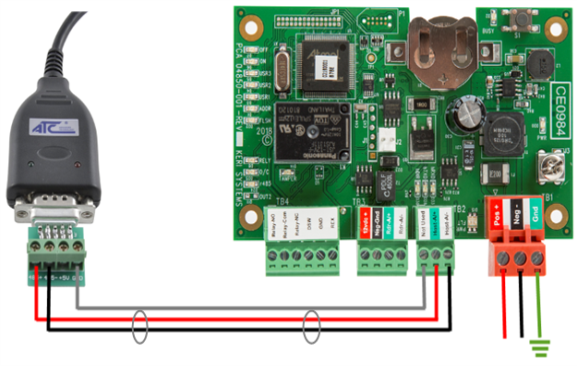
- Connect the USB end of the cable into an available USB port on the host PC.
- The adapter should be installed automatically and you should be able to find the device in Windows Device Manager.
- Connect RS-485+ of the adapter to TB2-RS-485 A+ of the controller.
- Connect RS-485- of the adapter to TB2-RS485 B- of the controller.
- Connect the network shield wire to the GND of the adapter. Do NOT connect the shield wire to the frame ground of any of the controllers is this may cause a ground loop.
Notes:
- Every system will require the USB-to-RS485 adapter for connection - even if you have just a 1 door system. The adapter, once installed will automatically be assigned a COM port and the auto-configuration automatically scans the PC for the assigned COM port - so it is very much 'plug-and-play'.
- When using multiple Neutron controllers, the adapter can be wired into the TB2 connector of any one of the controllers.
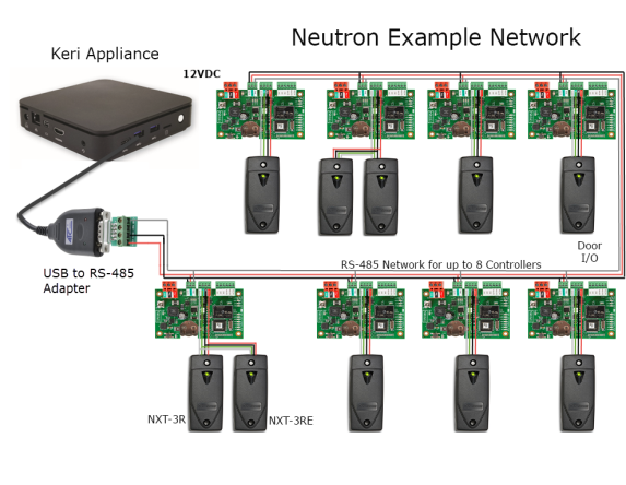
6.0 Neutron Network Schematic
This diagram illustrates an example system using the maximum number of 8 controllers.
The USB-to-RS-485 adapter connects to one of the Neutron controllers and the other Neutron controllers are hard-wired together on a RS-485 network.
Notes:
- The RS-485 network should be a multi-drop daisy-chain topography. Keri recommends against using a star or ring configuration.
- The maximum total RS-485 cable network length is 4,000ft/1200m.
- The recommended RS-485 cable type is Belden 9501 (shielded, stranded, twisted pair) AWG22 or greater.
7.0 NXT Reader Wiring
Note: Recommended reader cable is Belden 8723 (or equivalent), this is a 2-pair shielded,
stranded, cable (with a twisted RS-485 pair).
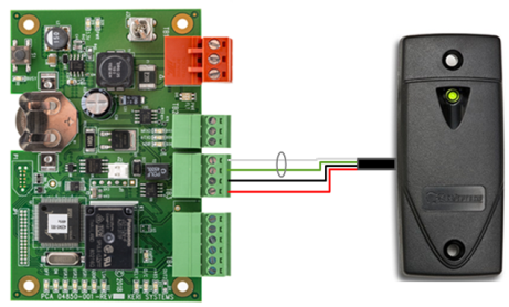
- Pin 1 - +12VDC Output (red)
- Pin 2 - Ground + shield (black)
- Pin 3 - RS-485 A/+ (green)
- Pin 4 - RS-485 B/- (white)
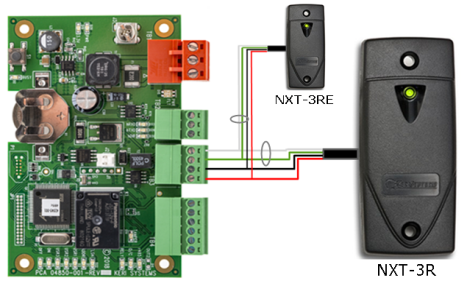
8.0 Wiring an NXT Exit Reader
9.0 Port Protection
Transorbs are provided with the controller ship kit. They are used to protect the controller from voltage spikes induced on the port wiring. Keri strongly recommends wiring in the transorbs provided as close as possible to the lock... Refer to the lock wiring diagrams (section 11.0).
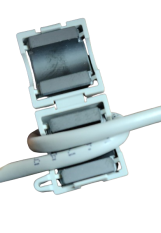
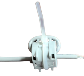
10.0 Ferrite Clamps for Transient Suppression
To reduce the possibility of transients being sent to the controller from the lock, Keri now supplies a ferrite clamp with all new controllers. This clamp should be placed close to the locking device with the lock cable looped around the clamp once and then sealed with a cable tie. A second ferrite clamp can also be added close to the controller, however it is generally not required. Installing the ferrite clamp is particularly important when installing a lock which is not from a recommended lock supplier (see important notes in the next section).
11.0 Lock Wiring
Important Notes When Powering Locks:
- The Neutron ship kit comes with a 1.8amp power-supply which is enough to power the
controller, 2 x NXT 1R/3R or 5R readers and a lock (with a maximum current draw of 1amp). - If you will be controlling a lock with a maximum current draw greater than 1amp you should power the lock separately.
- Maglocks should be on their own supply due to the power surge created by these locks when locking and unlocking that could affect controller operation.
- Keri recommends the use of door locks from dormakaba, ASSA, and Allegion, as well as from SDC and Dortronics. If you are not using a lock from a recommended supplier you must ensure that you install the ferrite clamp that is supplied with the controller.
11.1 Fail-Safe Lock Wiring
A fail-safe lock requires power to keep the door locked. So if power should fail at the lock, the door will unlock - allowing quick entry or egress. A typical fail-safe lock is a magnetic lock.
11.2 Fail-Secure Lock Wiring
A fail-secure lock requires power to unlock the door. If power fails at the lock, the lock will automatically lock and will not allow entry or egress. A fail secure door ensures a secured area remains secure regardless of the situation.
Note:
- Transorbs are also provided with the controller ship kit. They are used to protect the controller from voltage spikes induced on the port wiring. Keri strongly recommends wiring in the transorbs provided as close as possible to the lock... Refer to the lock wiring diagrams below:
- The Transorbs that Keri provides are non-polar; they can be installed in either orientation.
12.0 Isolation Relays
For locking devices that may induce heavy voltage spikes – Mag Locks and devices with heavy-duty solenoids such as turnstiles, vehicle gates, and overhead doors – Keri recommends using isolation relays. Keri has an Isolation Relay Kit (p/n IRP-1). Please refer to the IRP-1 Isolation Relay Installation Guide (p/n 01833-001) for detailed information.
13.0Request-to-Exit Input Connection
14.0 Door Contact Input Connection
15.0 Specifications
15.1 Neutron Controller Dimensions
- Neutron Controller PCB
- 2.36” H x 4.0” W x 0.78” D, not including wiring connectors - Neutron Enclosure
- 2.75” H x 4.25” W x 1.32”
15.2 Linear Power Supply Requirements
+ 12 VDC nom. (9-15 VDC)
15.3 Current Requirements at 12VDC
- 250mA for a Neutron controller
- 120mA for each NXT-1R, NXT-3R, NXT-4R or NXT-5R reader
15.4 Relay Contact Rating
- 1 A @24 VDC dry circuit
15.5 Operating Conditions
32°F to 150°F (0°C to 60°C) – 0% to 90% Relative Humidity, non-condensing
15.6 Battery/Memory Retentions
5-year lithium battery backup to support controller RAM and real-time clock
15.7 Recommended Cable Types
| Connection Type | Total Maximum Run Length | Recommended Cable Type |
| PC-to-ATC-820 Convertor | 10m | USB extension cable |
| ATC-820-to-Neutron Network | 500m | Belden 9501 (or equivalent) |
| Neutron-to-Neutron Controller | 1200m | Belden 9501 (or equivalent) |
| Neutron-to-NXT-Reader | 300m or 150m when using 2 readers | Belden 8723 (or equivalent) |
| Neutron Controller Power | 3m | Belden 8461 (or equivalent) |
| Inputs and Outputs | 300m | No specific requirement |
Notes:
- Cable resistance causes a drop in voltage at the end of long cable runs. Ensure the appropriate power and current for your device is available at the device at the end of the cable run. Heavier gauge cables reduces this effect.
- Earth-Ground - Use the shortest possible path from earth ground point to Neutron PCB. Connect the earth ground only to the designated pin on the terminal block. This is important as all transient protection for the unit is made through this earth ground connection. For unit protection, the earth ground connection should always be made first.
16.0 Controller Reset Procedure
Before adding the controller to your Visual Doors software, you should factory reset the controller. The factory reset will clear all configuration and event history (but will retain the controller's MAC address) so it can be found again using Auto-config.
17.0 Factory Reset Procedure
- Down-power the controller.
- Hold down the S1 button while applying power.
- Continue to hold down the S1 button...
- Release the S1 button when the BUSY LED (D2) stops blinking.
- The FLASH LED (D22) will then be solid red for approximately 30 seconds.
- The FLASH LED (D22) will go off and the offline LED (D7) will then be solid red.
- The controller is now reset and ready for setup.
Note: If you release the S1 button too soon, or too late then no reset will occur.
Related Articles
Neutron Full Reference Guide
1.0 Introduction Neutron a single-door controller type which is configured and managed using Keri's Visual Doors software. It is a small, low-cost, easy to install controller that supports 1 or 2 NXT readers (1 x entry and 1 x exit reader) and is ...Neutron Cable Requirements
Neutron Cable Requirements Reference Guide (attached)Neutron Comms Cable Reference Guide
1.0 Introduction The USB-to-RS-485 communication module (NEUT-CBL ) is used to provide communication to a Neutron controller network. It is a high speed USB-to-RS-485 - (2-wire, half duplex) adapter that uses the FDTI serial to USB chip. Using the ...Neutron Troubleshooting Guide
1.0 The Neutron Controller is Showing as Offline Verify the controller is powered-up. Verify the TB2 network connection terminal block is properly connected. Verify the wiring to the TB2 terminal block. If all controllers are offline ensure the ...Neutron Controller Setup in Visual Doors
1.0 Software Installation Notes When performing the Doors.NET installation, you should select the Full Installation (this installs all software components for a standard installation onto the PC, including the Neutron gateway). Alternatively, if you ...