NXT-MSC Controller - Controller Setup Guide
1.0 Introduction
 |
This document covers the basic setup of an NXT Mercury Powered (NXT-MSC) controller in Doors.NET or Borealis. It assumes your Doors.NET or Borealis system has already been setup.
Important Notes:
- A Doors.NET system should be licensed and the MSC gateway should be setup and online.
- A Borealis system should be setup and a hub should already be added and configured for Keri MSC or Mercury controllers.
- Once the NXT-MSC controller has been added to Borealis it will not be functional until the cloud subscription for the readers has been purchased.
- The new black-coloured PCB also has a QR code this can be used to add the controller to Borealis using the Borealis Connect app (covered in section 4.0).
- Once a controller has been added to Doors.NET or Borealis you should enter the controller's internal configuration and change the Auto Save setting to Restore from the Last Saved Settings. This is the recommended setting - whereas the default controller setting is: 'Clear all settings. Forced a Full Download'. This is explained in section 8.0.
Before adding the MSC controller, you should make a note of the controller's MAC address. The MAC address can be found on the white sticker in the lower left corner of the controller (near to the Ethernet port). The MAC address begins 00-14-34.
 |
Keri Public Statement on the Amazon Key
Keri Systems, Inc. has updated its policy regarding the integration of
We are pleased to inform you that Amazon has now provided official installation
This change reflects our commitment to supporting secure and flexible access solutions
Please note the following:
Keri Systems remains dedicated to providing robust access control solutions.
|
3.0 Adding the NXT-MSC Controller to Doors.NET
3.1 DHCP Address Assignment
When the NXT-MSC controller is powered-up and connected to the local area network (or
directly to your host PC via a patch cable). It will initially try and obtain a DHCP IP address.
If no DHCP address is assigned to the controller (i.e. if DHCP is not enabled on the network), then the controller will automatically set itself to a static IP address that begins 169.254. To import the controller using its default static IP address you would need to configure the host PC with an IP address in the same range as 169.254.x.x. You would then import the controller, set the controller to its required IP address and then set the host PC back to its original IP setting.
- Ensure the controller is powered-on and connected to the network.
- Near the lower-left corner of the controller PCB there are 2 network LEDs.
When the controller is connected to a network, LED D21 should be quickly flashing green, D22 should be solid red.

- Open the Doors.NET login window by clicking the client icon on the desktop.

- Login using the default username and password of admin/admin.
- Once logged in, go to Setup >> Hardware Setup then the All tab.

- You will see the MSC gateway at the top of the hardware tree.
- Right-click the gateway and select Scan or click the scan icon on the hardware ribbon bar.

- There is a utility built into the MSC gateway that will scan for all MSC
controllers. - As long as the host PC has an IP address in the same range as the controller's DHCP address, the MSC controller should appear almost immediately.
- If there are multiple controllers look for the MAC address that matches the one you have noted down.

3.2 Importing the Controller
- Select the controller from the list.
- Click the IMPORT button.

- Click Yes to confirm you wish to go ahead with importing the controller.
- The controller will be added to the system and will appear on the hardware tree.
- Click OK to complete the controller import.
3.3 Configure the Controller with a Static IP Address
Because the controller has been added to Doors.NET with a DHCP address it is now highly recommended that you configure the controller with a static IP address.
Note: Before assigning the controller with a static IP address you should ensure that the IP address is available and not already assigned to a different device on the network. This can be done by opening a command prompt on the host PC and then pinging the IP address that you wish to assign the controller. If you do not get a reply from the entered IP address then you will be able to assign it to the controller.
Doors.NET has a feature that allows you to program the controller's internal configuration (including the assigned IP address) and this feature is accessed via Design Mode.
- From Doors.NET, click the Design Mode icon in the upper-left corner of the admin client.

- The client title bar will indicate that Design Mode is enabled.

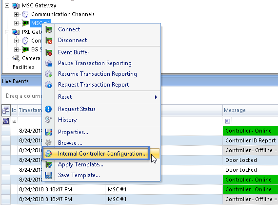
- Return to the hardware tree (Setup >> Hardware Setup >> All) if it is not already open.
- Right-click the new controller and select Internal Controller Configuration.

- From the Web Page selection drop-down list, select Network.

- Click the refresh icon.

- The controller's programmed network settings will appear on the right side of the window.
- You will see that the controller is set to DHCP and the assigned DHCP address is also displayed.

- Change the Network Method to Static.
- Enter the Static IP address that you wish to assign to the controller.

- Click the blue save
 icon located above the controller network properties to save the network settings.
 - Click the APPLY and REBOOT button which will have appeared.

- Click YES to proceed.
- The static IP address will be assigned to the controller. The controller will reboot and within a few seconds will come back online in Doors.NET with the new static IP address.
- You can now close down the controller internal configuration window.
3.4 Update the Controller Firmware
A brand new controller will not require a firmware update but you may need to update the
firmware on an older controller.
If a controller does need a firmware upgrade you will see the following message in live events:

- Go to the Doors.NET hardware setup screen.
- Press the <F1> key on the keyboard.
- The built-in help file will be initialized.
- Select English as the language. Then OK.
- The help file will open up on the Controllers page.
- From the table of contents on the left, expand Hardware Setup.
- Expand Firmware Upgrading.
- Click on Controller Firmware Upgrading.
- Scroll down to the NXT-MSC controllers and you will see the instructions for upgrading the controller firmware.

4.0 Adding the NXT-MSC Controller to Borealis
The following steps explain how to add an NXT-MSC controller to Borealis. It assumes that you have already followed the steps to add an NXT-MSC site to your system. During the steps to claim the hub you will select the site that the hub will be associated with.

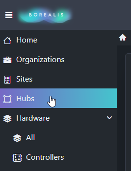
- From the main menu, click on Hubs.
Your hub will appear in the list.
- Click the Actions drop-down menu on the right and select Scan. Or click the SCAN button.

The scan function will scan the local network for controllers.
- After a few seconds, controllers will appear in the list.
IMPORTANT NOTE: When adding NXT-MSC controllers they will be assigned with a DHCP IP address.
- Place a check mark against the controllers that you wish to claim.
- Enter a name for each of the controllers that you wish to add.

- Click the CLAIM button.

At the top of the screen you should see a message stating that the controller(s) has been successfully claimed.
- The controller can be viewed via Hardware >> Controllers. Within a few seconds the controller should be online.
5.0 Adding a Controller Using the Borealis
Connect App
Borealis also has an app that allows you to easily add a controller to your system using the QR code printed on the lower right corner of the controller.

- Download the app to your Android or iOS device (scan the following QR code or search for Borealis Connect).
- When you open the app, you will be prompted to login to your Borealis system.
- Enter your registered Borealis e-mail address and password. Then click SIGN IN.
- Select your system.
- Next, click the ‘QR enroll’ button.

- Scan the QR code on your NXT-MSC controller.
- A controller import form will appear.

- Enter a name for the new controller.
- Leave the IP address field blank (as a DHCP address will automatically be assigned to an NXT-MSC controller).
- The controller's unique MAC address will be displayed.
- Beneath the MAC address, is the specific controller type.
- Tap the target hub name field, and select your Borealis hub.
- Click the ADD button.
- You will see a message stating the controller has been successfully added.
- You can now log into Borealis via a web browser (either from your smart device or a PC).
- Within a short period of time, the controller will be online. If the controller does not come online within a few seconds click the SCAN button on the Hub screen. Once the scan is complete the controller will be online.
6.0 Update the Controller Firmware
The following steps explain how to update the firmware on an NXT-MSC controller in Borealis. If a controller requires a firmware upgrade you will see a firmware update required event in live events.

- From the main menu, click on Hardware>> Controllers.
- On the right side of the screen use the controller's Actions menu and select Flash.
- Select the latest firmware file from the drop-down list (for example, v1.296).
- Click the SAVE button.
- The new firmware will now be sent to the controller.
- During the upgrade the controller will go offline for a few seconds.
- The firmware upgrade will be completed within a couple of minutes.
- The new firmware version will then be displayed on the right side of the Controllers screen.

7.0 Modifying the RTE Input Setting
If you are not using Request-to-Exit (RTE) inputs you will notice that the lock relays will activate when the controller has a memory reset. The reason is because by default, the RTE inputs are set to Normally-Closed. When the controller does a Power-On-Self-Test it checks the status of the inputs and if the circuits are open then the RTE function will activate. To prevent this from happening you should do the following on each reader:
- Expand the controller and then the controllers bus.
- Highlight one of the controller's readers.
- In the reader properties located on the right, locate the REX 1 Properties.
- In the Circuit Type field change the setting from Unsupervised, Normally-Closed to Unsupervised, Normally-Open.
- Then save the reader properties.

- The next time the controller has a memory reset the lock relays will remain inactive.
8.0 Auto Save Setting - Restore From Last Saved Setting

8.1 Internal Controller Configuration In Doors.NET
- Enable Design Mode via the icon in the upper-left.

- Locate the new controller on the hardware tree.
- Right-click the controller and select Controller Internal Configuration.
- From the web page menu, select Auto-Save.
- Ensure Auto-Save is enabled.
- Set the Controller Start up Routine to Restore the controller from its last saved settings. This is the most secure option - For most systems the recommendation is for Restore to be enabled.
8.2 Internal Controller Configuration In Borealis
- From the main menu, click on Hardware >> Controllers.
- The Controllers screen will appear.
- On the right of the screen, click on the Controller's Actions menu and select Configure.
- The controller's Internal Configuration form will appear.
- Use the drop-down menu to select Auto Save.
- Ensure Auto Save is enabled.
- For the Controller Start Up, select - Restore from the last saved settings. This is the most secure option - For most systems the recommendation is for Restore to be enabled.
- Save the controller settings.
- Click the Apply and Reboot button. The controller will reboot and will momentarily go offline.
9.0 Factory Reset Procedure
- Ensure the J3 jumper is across both pins.
- Press the white S1 button - the D MODE LED will go solid green.

- While the D MODE LED is still green, down power the controller.
- Press and hold the white S1 button and apply the power.
- The following LEDs will be flashing in an alternating sequence (Reset + ULED2 + ULED4) then DMODE + ULED4.
- Continue to hold down the S1 button for approximately 20 seconds.
- Release the S1 button and the all LEDs will initially go off.
- You will see various LEDs go on and off for a few seconds then only the Reset LED will be flashing on and off.
- The controller's ram is now reset. The 4 green LEDs to the right of the J3 jumper should also now be on.
- The controller will either be set to a DHCP address or it will automatically be set to a static address in the range of 169.254.99.X if it does not receive a DHCP address within 1 minute.
10.0 Further Setup and User Information
10.1 Doors.NET Help File
Once the controller is added to the Doors.NET software you are ready to start configuring other aspects of the system, such as; setting up access groups and time schedules and adding cardholders. All these topics and more are covered in the comprehensive help file which is included with Doors.NET.
The quickest and easiest way to access the help file is to press the F1 key while on any of these screens. If you are on the cardholders screen for example (Home >> Cardholders) then press F1, the help file will automatically open up on the Cardholders section.

10.2 Guided Support
Keri Systems has a Guided Support platform that intuitively guides you to appropriate setup information for Doors.NET, Borealis and hardware setup of all controller and reader types. Guided Support also has useful sections troubleshooting:
Guided Support URL: https://kerisys.com/guided-support
10.3 Knowledge Base
There is also the knowledge base which has setup and installation guides as well as data sheets, product specifications, training videos and application notes.
- General Knowledge Base URL: help.kerisys.com
- Borealis Knowledge Base URL: borealis.kerisys.com
10.4 Borealis Answer Bot
 P/N:01238-003 Rev D |
Related Articles
NXT-MSC - OSDP Reader Support
1.0 Introduction OSDP (Open Supervised Device Protocol) is an access control communication standard developed by the Security Industry Association (SIA) to improve interoperability among access security products and is being endorsed by all leading ...NXT-MSC Controller - Setup an Airlock/Mantrap
1.0 Introduction The airlock features is available on NXT-MSC or Mercury SCP controllers when Area Control is enabled on the license. This is so that you can set up two or more areas as 'airlock' areas. Anti-passback is not required for airlocks to ...How do I Setup an NXT-MSC Controller?
How do I setup an NXT-MSC 2-door or 4-door controller in the Doors.NET software? An NXT Mercury-powered (NXT-MSC) controller is added to Doors.NET via an Ethernet connection and there are two options; either the controller obtains its IP address ...NXT-MSC - Controller Internal Configuration
Effective from Doors.NET v4.0.3 it is now possible to make various controller configuration changes within Doors.NET rather than via a web browser. This section explains how to access the controller internal configuration and which configuration ...NXT-MSC Controller - Setup Anti-Passback
The Anti Passback (APB) feature provides one-way card access into and out of a secure area. It prevents a cardholder from using their card and then passing that card back to someone in order for them to gain unauthorized access. Local APB is ...