OSDP Reader Support with Real Mercury Hardware
1.0 Introduction
OSDP (Open Supervised Device Protocol) is an access control communication standard developed by the Security Industry Association (SIA) to improve interoperability among access security products and is being endorsed by all leading access control manufacturers.
Doors.NET v4.9.0 (and later) supports OSDP readers when using the NXT Mercury controllers (NXT-MSC) or the Mercury LP-Series door controllers. OSDP readers, like Keri NXT readers, are fully supervised RS-485 readers and hence are more secure than the most common access control communication protocols. You can also add an OSDP Exit reader by wiring a second reader into the same bus of the controller. The entry reader is addressed as 0 and the Exit reader is addressed as 1, 2 or 3.
Addressing and adding the readers is covered in this document along with an explanation about reader status and supervision.
OSDP Main Features
- OSDP - Two-way AES 128-bit encrypted communications.
- OSDP - The reader (communication status) is supervised - you will know immediately in the software if the reader is compromised and goes offline.
- OSDP reader cable runs can span long distances (up to 4,000 feet).
- You can have more than one reader on the cable run (adding an exit reader).
- Flash firmware makes the readers upgradeable and extends the life cycle of the reader.
- Open standard - Proprietary solutions are often not favored by modern enterprises.
- When readers are OSDP it enables better interoperability among different access control products.
- A trusted standard that is actively being developed by the SIA (Security Industry Association).
2.0 Reader Extension Cable Requirements
The recommended cable type for the reader extension cable is Belden 8723 (or equivalent) - this is a 2-pair shielded, stranded, twisted cable. AWG 24 wire or larger (note that increasing the wire gauge does not increase the total network length) - The total cable run length is 4,000 feet/1,000 meters.
3.0 OSDP Reader Wiring
OSDP Reader Wiring (for example, to an LP-1502 or LP-4502 controller).
 Note: OSDP readers will not always follow the same wire color conventions as shown in the image below. The TX+ and TX- wires may be a different color. Refer to the reader's installation guide to be sure.
Reader 1
| TB 8-1 | Ground |
| TB 8-2 | TR- (A) |
| TB 8-3 | TR+ (B) |
| TB 8-4 | - No connection - |
| TB 8-5 | - No Connection - |
| TB 8-6 | Reader power |
Reader 2
| TB 9-1 | Ground |
| TB 9-2 | TR- (A) |
| TB 9-3 | TR+ (B) |
| TB 9-4 | - No connection - |
| TB 9-5 | - No Connection - |
| TB 9-6 | Reader power |
4.0 Reader Addressing
IMPORTANT NOTES:
- By default, most OSDP readers will be addressed as 0 (so they will be seen by the controller as a standard entry reader). This means if you were to initially connect 2 new readers to the same bus they would both be addressed as reader 0 and will not communicate.
- Some of the older OSDP reader types do not support auto-discovery and so you will need to refer to the manufacturers supporting documentation for details about manually setting the reader address and the BAUD rate locally at the reader.
- Once a reader has been configured as an OSDP reader nothing else can be connected to that bus (except for a second OSDP reader).
5.0 Adding a Single OSDP Reader
This assumes you already have a Mercury controller added and online in Doors.NET and it also assumes both readers support auto-discovery.
- From within Doors.NET, go to Setup >> Hardware Setup >> All to display the hardware tree.
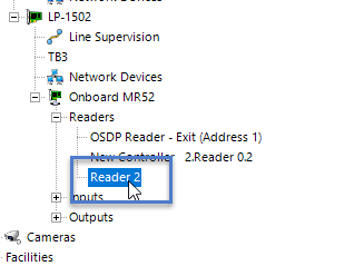
- Expand the controller and select the reader that is an OSDP reader. The reader properties will be displayed on the right.
- Ensured that Advanced View is enabled for the reader properties.
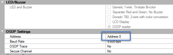
- Scroll down the properties until you locate LED/Buzzer. Set this to 'OSDP reader'.
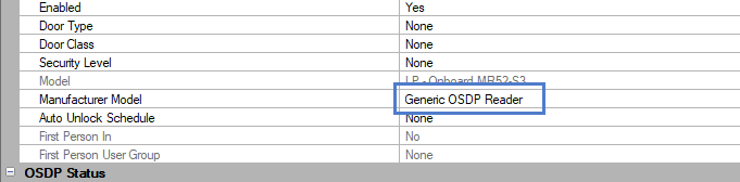
- The reader's Manufacturer Model at the top of the properties will automatically set the model as Generic OSDP reader.
- Save the reader settings.
- As you will see, in the previous image, the default address number is 0 - so if you only have a single reader connected, the controller will start communicating with the reader as soon as the reader settings have been saved.
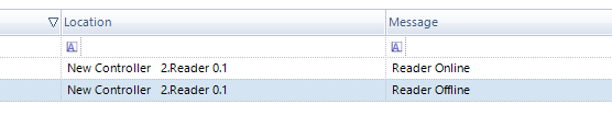
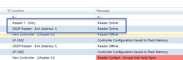
- In live events, you should see a reader online event.
6.0 Adding an OSDP Exit Reader
When adding a second reader to the bus you should setup the readers individually as per the following instructions - (because communication will not be possible when both readers have the same default address 0). The following steps require you to be logged into Doors.NET as a system administrator. If the system will be using multiple entry and exit readers you could configure (and label) all the readers as either exit readers or entry readers prior to going to site.
6.1 Add and Configure the OSDP Exit reader
When adding two OSDP readers to the same bus (to control the same door), the easiest method is to add and configure the Exit reader and for the Entry reader to initially be disconnected.
- Connect ONLY the exit reader into the controller's bus.
- Add the reader following the steps defined in the previous section.
- When the reader is online, in the reader properties, set the reader to address 1.
- Save the reader settings.
- The reader will go offline.
- Right-click the reader in the hardware tree and select OSDP >> Auto-Discovery.
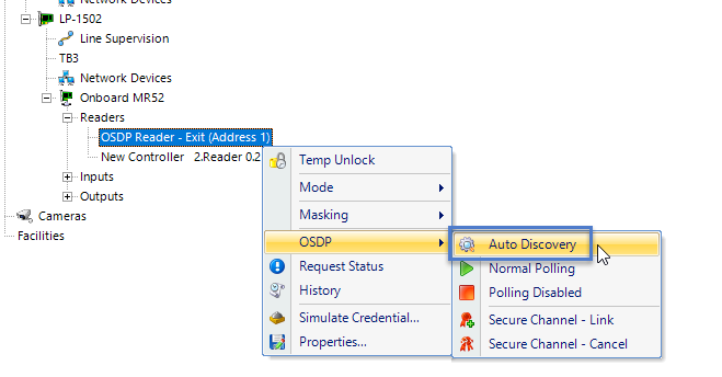
- Wait a few seconds and then the reader will come back online and will be addressed as number 1.
- Next, click the Design Mode icon to enable design mode.

- Right-click the entry reader and select OSDP >> Polling Disabled.
- The OSDP Exit reader will then be offline.
6.2 Setup and Add the Entry Reader Second
Once the exit reader has been addressed as number 1 and is online, you can do the following:
- In Doors.NET, select the 'Onboard MR52'
- From the hardware browser ribbon bar at the top of the screen, select Add ACR.
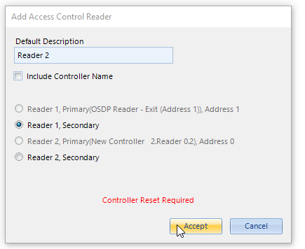
- A dialog box will appear.
- Leave the default selected reader selected (Reader 1, Secondary).
- Click the ACCEPT button.
- At the bottom of the dialog box you will see in red text that the controller will require a memory reset.
- Confirm the prompt to reset the controller.
- The additional reader will be added to the hardware tree.
- Select the new reader that has been added.
- In the reader properties, ensure advanced view is enabled.
- Scroll down to the OSDP reader settings.
- The reader should already be configured as address 0.
- Connect the entry reader to the same bus that the exit reader is connected.
- Right-click the entry reader again and select OSDP >> Normal Polling.
- Both OSDP readers should now be online.
7.0 Auto-Discovery Change Address
The newer OSDP readers support 'auto-discovery' this will allow you to change the reader's address from the Doors.NET soft ware (again, this requires you to be logged into Doors.NET as a system administrator and you will need to momentarily enable Design Mode).
- Enable Design Mode (via the Design Mode icon):
- Select the reader in the hardware tree.
- In the reader properties, change the reader address number.
- Save the reader settings.
- Right-click the reader in the hardware tree and select OSDP >> Auto-Discovery.
- The reader will momentarily go offline. Once it is back online it will be configured with its new address.
8.0 Set the Correct LED Modes
When you add an OSDP reader, the default LED mode (when the reader is locked) is slowly flashing red. The following steps explain how you can set a different LED mode to the readers (for example, to match a Standard Wiegand reader which will typically display an amber LED when locked.
- Ensure Design Mode is enabled.
- Close and re-open the hardware tree if it is already open.
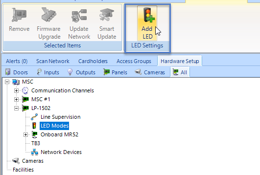
- On the hardware tree you will see a node named 'LED Modes'.
- Select this new node.
- From the ribbon bar at the top, click Add LED icon.
- Select the Undefined entry that appears on the hardware tree.
- The LED Mode properties will be on the right.
- From the LED mode drop-down list, select Mode 2.
- From the Reader Function drop-down list, select Locked.
- Set the ON color to amber.
- Set the ON time to 500 ms.
- Set the OFF color to amber.
- Set the OFF time to 500 ms.
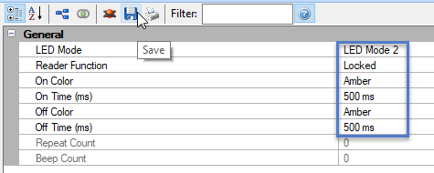
- Save the LED Mode settings.
- When the reader is locked, the LED will then be solid amber.
- You can then configure how you wish for the LED to behave for each of the other reader functions.
- For example, when the reader is unlocked you could either have a solid green LED or if the reader is in Card + PIN mode you could configure the reader LED to alternate between flashing red and green.
9.0 OSDP Reader Supervision
Because the OSDP readers are fully supervised, if the reader is disconnected there will be an event displayed in live events.
You can configure this event type to generate a sound alert at the PC or you could configure an e-mail or SMS message to be immediately sent out to a designated recipient.
10.0 OSDP Status Information
- The Doors.NET software will detect the reader vendor, the model, the version number and the reader serial number (which you can view by selecting the reader in the hardware tree). The reader properties display on the right.
- Scroll down the reader properties and locate OSDP Status.
- The reader vendor and model details will be displayed.
11.0 OSDP Reader Firmware Upgrading
To be implemented in a future Doors.NET release.
Related Articles
Mercury - Hardware Overview
EP Series Controllers LP Series Controllers MP Series Controllers Mercury I/O and Door Modules Note: Doors. NET supports the Series 2 modules (green PCBs), the Series 3 modules (red PCBs) and the Series 4 modules (black PCBs). All series of modules ...Mercury - Series 3 Hardware Notification
1.0 Introduction Mercury is updating all their controllers and supporting peripherals with series 3 hardware revisions (the red coloured boards) and will no longer being supplying the series 2 hardware (green coloured boards). However, the series 3 ...Mercury LP Series - Full Reference
1.0 Introduction This section explains how to setup and configure all controller settings and advanced options. All these settings can be found either by logging into the controller via a web browser or by accessing the controller's 'internal ...Mercury MR52 (Dual Door Module) Setup
1.0 Introduction The Mercury MR52 is a dual door, dual reader module that connect to Mercury EP, LP or MP controllers via 2-wire RS-485. The module supports 2 card readers, including OSDP readers and it has 8 inputs and 6 relays. Four of the inputs ...Mercury MR16IN Module Setup
1.0 Introduction The MR16IN Input Control Module (ICM) processor provides sensor interface and input controls for security/access control, elevator control floor select and other applications. The module has 16 inputs for supervised contact ...