Program an Output to Follow an Input
1.0 Introduction
To program a Global Linkage action you must have the Global Linkage feature enabled in your license.
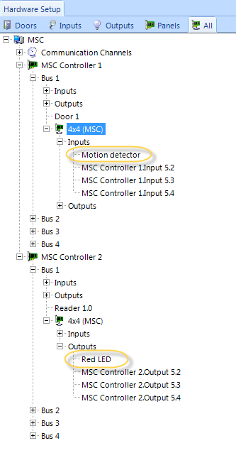
This example uses a monitor point (input) to activate a control point (output relay). The input can be a monitored door a motion detector and the output can be a red led or a buzzer. The LED or the buzzer would provide an indication that the door has been opened, or if there has been movement detected in a secure area.
This example uses an input and an output on NXT 4x4 modules. But you can, of course, use inputs and outputs on a satellite board of PXL controllers.
Both controllers in this example have a 4x4 module wired into bus #1.
2.0 Macro Setup
- From the Home tab >> Automation ribbon click Global Linkage.

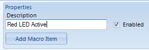
- Click the Add New button to add a new macro. In the Description create a name for the Macro (Red LED Active), then save.
- Click the Add Macro Item button, create a name (Output ON). From Macro Item type select Control Point, select the Gateway,
the controller and the specific output you wish to use, then set it to On.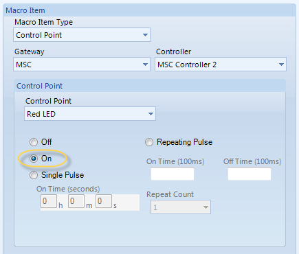
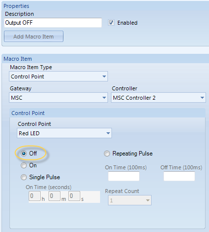
- Repeat the previous process to create a second Macro and rename it (Red LED Inactive). The Macro item type will be Output OFF. Select the same Control Point again but this time set it to Off.
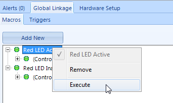
- You will now have two Macros defined in the list. The first one to Activate the output, the second will De-activate it. At this point you can test the functionality of each by right-clicking and selecting Execute.
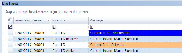
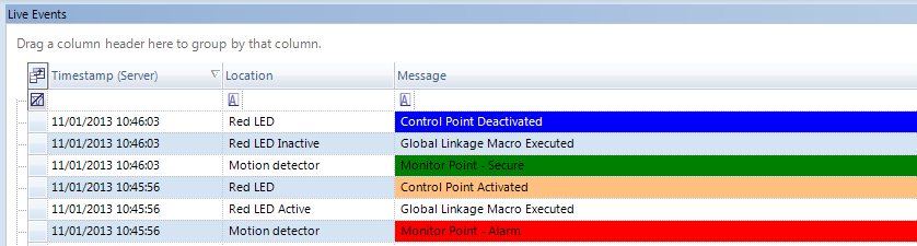
- As well as the physical relay changing state on controller 2 you should also see associated Live Events indicating what is happening.
3.0 Trigger Setup
- Click the Triggers tab, click add new then create a name for the trigger (i.e Motion Trigger).
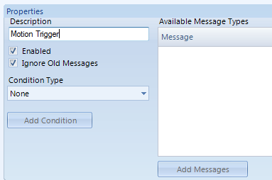
- From the Condition Type drop-down list select Monitor Point and click the Add Condition button.
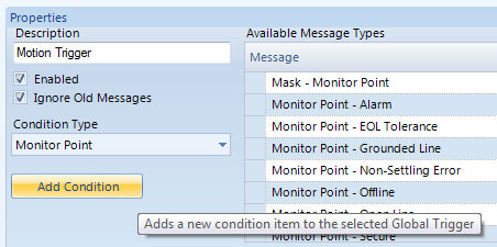
- Click the new condition to highlight it and give the condition a description (Input Active). From Available Message Types click Monitor Point - Alarm then click the Add Messages button.
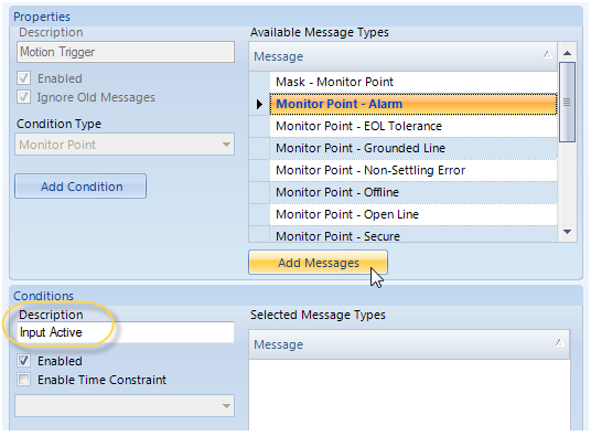
- The message will appear in the Selected Message Types pane. The last thing for the trigger setup is to select the Macro that it will action. Chose the appropriate
Macro from the drop-down list.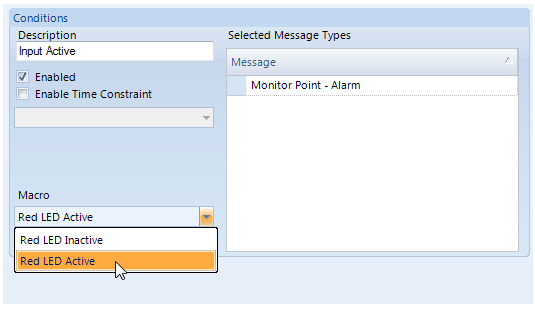
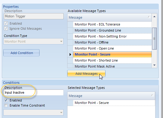
- Click Add Condition again. The Monitor Point - Secure condition can be assigned to the same trigger but will action the second Macro (to de-activate the Red LED output).
- Highlight the second condition and give it a description (i.e Input Inactive). From the Available Message Types select Monitor Point - Secure, then click the Add Messages button.
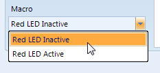
- Select the other Macro from the Macro drop-down list.
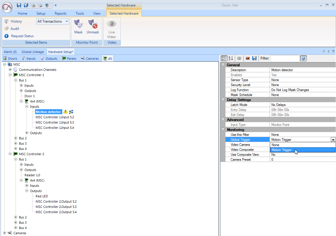
- Now that the configuration is complete you just have to highlight the Trigger input in the hardware tree. In the Monitoring section of the input's properties use the Global Trigger drop down list and select your newly created Global Linkage trigger. Finally click save.
- Activate the input on controller one to trigger activation of the output on controller 2. If the procedure fails to operate. Select the controllers (individually) from the hardware tree, right-click and select Reset Memory.
Related Articles
Local Linkage - Program an Output to Follow an Input
1.0 Introduction A basic Local Linkage example is to program an output on the system to follow an input, so that when the input goes active the output automatically goes active. When the input goes inactive then the output also goes inactive. Prior ...Change Card Reader Mode from an Input
1.0 Introduction A basic Local Linkage example is to program an output on the system to follow an input, so that when the input goes active the output automatically goes active. When the input goes inactive then the output also goes inactive. Prior ...Basic Input/Output (I/O) Control
Basic Input/Output Control 1.0 Introduction The standard version of Doors.NET provides basic input/output control for general purpose inputs and outputs when using standard NXT, PXL, NXT Mercury-Powered (MSC) or Mercury (SCP) controllers. The ...MR16IN - Input Control Module Setup
SCP-MR16IN-S3 (Input Control Module) Setup The Input Control Module (MR16IN-S3) processor provides sensor interface and output controls for security/ access control and other applications. The controller has 16 input channels for supervised contact ...Setup Outputs
The Setup Outputs process allows you to configure the output type and monitoring parameters. 1.0 Via the Outputs tab Under the Hardware Setup tab, Click the Outputs tab. The Selected Hardware tab is then loaded on the ribbon . 2.0 Via the Hardware ...