PXL-500 Setup in Doors.NET
1.0 Introduction
This section covers the basic configuration of PXL controllers in Doors.NET software. It assumes Doors.NET has already been successfully installed on your host PC, the software license has been activated, and the PXL gateway has been configured for your controller type.
Note: PXL-based sites with the following types of controllers are NOT supported in Doors.NET at this time:
- PXL-510 controllers for alarm panel control
- PXL-250 controllers (this product line is obsolete)
2.0 Important Note
|
3.0 Replicating Sites Mode in Doors.NET
Doors.NET can replicate Doors32’s Sites mode by using multiple primary controllers. This allows you to maintain the Sites mode style organization. Doors.NET can support up to 64 primary controllers, replicating up to 64 Sites, and each primary controller can have up to 127 Secondary controllers. Doors.NET allows all sites to be monitored, administered, and updated concurrently; something that is not possible in Doors32.
4.0 Adding a PXL-500 Primary Controller to the PXL Gateway
To use a PXL controller network you must first establish a connection to the Primary controller. Communication to the Primary controller can be made via a serial, Ethernet, or modem connection. Each Primary controller will have a communications channel enabled, setup, and assigned to it. All Secondary controllers are then added to the system using auto-configuration.
- Open the Doors.NET login window by clicking on the client icon on the desktop.

- Login to the software using the default username and password of admin / admin, then click Connect.
- Click Setup >> Hardware Setup >> All.tab then click Hardware Setup.

- Highlight the PXL gateway to view its properties in the grid.
- With the gateway highlighted, click the Add PXL icon.

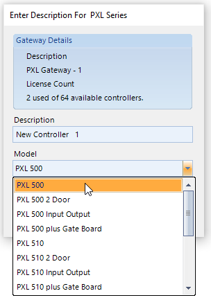
- Enter a description for the controller.
- Select the exact PXL model type from the Model drop down list. This allows you to manually configure an entire system (i.e name and configure doors and setup and assign access groups) before going to
site, or before the controllers have even been installed on the site.
Note: Manually added controllers are added as Keri proprietary controllers, not Wiegand. If using Wiegand PXL controllers you MUST perform an auto-configuration once the controllers are online. This is required
to detect the correct Wiegand reader types.
5.0 Configure the Communication Channel
If you are upgrading from Doors32 and your existing installation uses sites mode, Doors.NET accepts multiple Primary controllers allowing you to continue to maintain the sites mode style organization. Each site’s Primary controller will require its own communication channel.
There are three different communication channel types available, one of which must be assigned to the Primary PXL controller for establishing communication to the PXL network. All Secondary controllers are added to the software using Auto-configuration.
You can communicate to a PXL using Doors.NET via:
- a serial connection (from the PC’s physical COM port, a recommended USB to Serial adapter, or a Keri USB Comm Module).
- a modem connection.
- over Ethernet using a LAN module such as the LAN-520.
Note: Because of the delayed nature of a dial-up connection, situation manager, global lock and global unlock features are not supported when using a modem connection to a PXL network. These features are only available when using a serial or Ethernet connection.
Follow the set of instructions for each site according to your communication method.
6.0 Serial Connection
- Highlight the Communication Channels node in the hardware tree.
- Click the Serial Communication Channel icon.

- A channel named “New Channel” appears in the hardware tree.
- Highlight the new channel so you can view its properties in the grid.
- Double-click False to change it to True.
- Set the COM port number that corresponds to the serial device being used. If you are unsure what COM port to use, go to Device Manager on the host PC and expand the node Ports – Com & LPT. If the COM port is correctly installed/enabled your device will have its assigned COM port showing in parentheses, i.e. (COM3).
- Give the communication channel a descriptive name.
- Click save and the channel settings is added to the database.
- Highlight the Primary PXL controller in the hardware tree.
- In the controller properties > Communication Settings > Communications Channel select the new channel from the drop-down list.
- Click the save icon, within a few seconds events should appear in Live Events signifying that the Primary is online.

7.0 Modem Connection
- Highlight the Communication Channels node in the hardware tree.
- Click the Modem Communication Channel icon.

- A channel named “New Channel” appears in the hardware tree.
- Highlight the new channel so you can view its properties in the grid.
- Double-click False to change it to True.
- Set the COM port number that corresponds to the serial device being used. If you are unsure what COM port to use, go to Device Manager on the host PC and expand the node Ports – Com & LPT. If the COM port is correctly installed/enabled your device will have its assigned COM port showing in parentheses, i.e. (COM3).
- Give the communication channel a descriptive name.
- Click save and the channel settings is added to the database.
- Highlight the Primary PXL controller in the hardware tree.
- In the controller properties > Communication Settings > Communications Channel select the new channel from the drop-down list.
- Enter the phone number for the modem attached to the Primary controller at the remote site.
- Click the save icon, within a few seconds transactions should appear in Live Events signifying that the Primary is online.
Note: Once connected, the modem line stays connected until manually disconnected. Depending upon your phone system, this may result in a large phone bill.
8.0 Ethernet Connection
Note: The LAN-520 unit must already be programmed with a static IP address, gateway, and subnet prior to adding the Network Communication Channel to the PXL gateway.
- Highlight the Communication Channels node in the hardware tree.
- Click the Network Communication Channel icon.

- A channel named ‘New Channel’ appears in the hardware tree.
- Highlight the new channel so you can view its properties in the grid.
- Double-click False to change it to True.
- The default Controller and Network Timeout values do not need to be changed.
- Give the communication channel a descriptive name.
- Click save and the channel settings will be added to the database.
- Highlight the Primary PXL in the hardware tree.
- In the controller properties > Communication Settings > Communications Channel select the new channel from the drop-down list.
- A Network channel selection will allow you to then input the IP address for the LAN-520. The port number is also set to the LAN-520 default of 10001.

- Click the save icon, within a few seconds events should appear in Live Events signifying that the Primary is online.
9.0 Perform an Auto Configuration
To detect Secondary PXL controllers on the network you must perform an auto-configuration. Auto-config is used to automatically retrieve the controller/door information from the PXL network and then populate Doors.NET database with the hardware details.
- To perform the auto-config, highlight the Primary controller in the hardware tree.
- Click the Auto-Config button.

- In the Status Message grid you should start to see regular transactions stating: “PXL Primary is searching for Secondary controllers.” It should take no longer than 2 or 3 minutes for the Primary controller to detect all the slaves on the network. The Primary controller always looks for the maximum possible 127 Secondary controllers.
- When auto-config has completed, the detected controllers appear in the Available controllers grid, as shown below.

- The final step is to click the Apply button.
- A prompt appears confirming how many controllers are selected. Click Yes and auto configuration will then complete.
- Once complete, close the Auto-Config tab and return to Hardware Setup > All.
- Double-click on the Primary controller to expand it and you will see all the Secondary controllers listed.

Note: Don't worry that the controllers are not listed alphanumerically... They will be once you have exited the client and logged back in.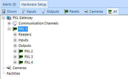
- To begin with, the Secondary controllers all have Update Required icons displayed next to them. You do not have to do anything because in the background the controllers will be updated one at a time.
- Keep your eye on the Live Events grid and you will see multiple network update messages. The update icons will disappear when each of the controllers have been updated.

- Sites with no cardholders added should take no longer than a few minutes for the initial update to complete. The update will be longer for existing (converted sites) - or for sites that have cardholders already enrolled.
Your system is now ready for operation.
10.0 Set PXL Network Timeout Settings
The recent Doors.NET v3.5.1.18 release includes a number of PXL gateway changes that improve data throughput speed between Primary controller and host computer. As a part of this release a body of network characterization work was performed and optimum values were determined for controller timeout and network timeout. These new values are implemented as part of a new PXL installation. However, they are not updated if a software upgrade is performed from Doors.NET software revisions prior to v3.5.1.18. This results in increasing network communication degradation as the number of Primary controllers increases. To correct this issue the Controller Timeout and Network Timeout values must be changed to the optimum values.
- Click Setup > Hardware Setup.
- Expand the Communication Channel tree.
- Select the Network Channel.
- In the grid change the Controller Timeout value to 20,000 (previous default value was 800).
- In the grid change the Network Timeout value to 20 (previous default value was 5).
- Save these changes.

11.0 Factory Reset Procedure
If you are powering-on the controller for the first time or have just changed the EPROM/PIC, the PXL controller's RAM must be reset before performing any other action. This clears any spurious information that may be in the RAM in preparation for entering your access control information.
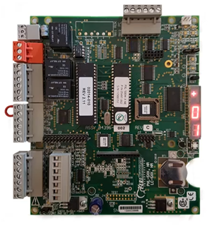
- Before applying power, insert a jumper across both pins of JP10.
- Press down the white S1 button and keep it pressed down while you apply the controller's power.
- Keep S1 pressed for approximately 5 seconds.
- You will hear a double beep from the reader attached to the controller indicating the controller's RAM is reset.
- Release the S1 button.
- Remove the power from the controller and put the jumper back onto 1 pin of JP10.
- Apply the controller's power. The controller is now ready to be powered up for use.
Note: Resetting the RAM completely erases all access control information. Before resetting a working controller, ensure you can communicate to it from the software because an update will need to be performed to send the information back to it.
12.0 Viewing the PXL Controller Address
To view the controller's programmed address, click the S1 button. The controller's address will appear on the address display for 2 to 3 seconds.
13.0 Setting the PXL Controller Address
To set the address to the PXL controller:
- Verify the jumper to JP10 is NOT installed (if the jumper on JP10 is installed, the controller's RAM will be reset when the power is turned on).
- Hold down the S1 options button and turn the controller's power on.
- The beeper for the reader attached to the controller will beep as the power comes on.
- Release the S1 button.
- The address display LEDs then become active and the controller's address can be set (the address range is from 1 to 128) - the Primary Controller must be set to address 1.
- Quickly double-pressing S1 toggles between increasing and decreasing the controller's address. The top LED character will display either a + or a - to show which direction is active. A single click of S1 changes the controller's address by 1. If you're at address 128, a + click will roll the address over to 1; conversely, if you're at address 1, a -1 click will roll the address over to 128. Holding down S1 will rapidly scroll through the addresses.
After the new address has been set, you must wait approximately 30 seconds after releasing the S1 button. There is a timer in the controller's firmware that assumes that after 30 seconds of inactivity (no address clicks), the entered address is the desired address for that controller. After 30 seconds you will hear a double beep from the reader indicating the controller has recognized and accepted the new address and the address LEDs will turn off.
Note: When the controller's address is changed the RAM is automatically reset (so an update will need to be performed on the controller.
To view the controller's programmed address, click the S1 button. The controller's address will appear on the address display for 2 to 3 seconds.
Related Articles
PXL-500 Setup in Doors.NET with a LAN-520
1.0 Introduction The following are basic setup instructions for the LAN-520 module. Some settings may not apply to every application. Note: The LAN-520 AESP is an updated version of Keri’s LAN-520X device. If you are using the new NC-485X Network ...Doors32 to Doors.NET Networking Setup Procedure
1.0 Introduction The NC-485 module was designed to provide RS-485 connectivity across an Ethernet network and to simplify the management of a Doors32 system - as it allowed multiple PXL networks to be combined and then administered and monitored as a ...PXL-500 Setup in Doors.NET With a USB-Serial Adapter
1.0 Introduction This guide explains how to setup a connection to a PXL-500 Primary controller using a USB-serial adapter. The adapter used in this example is the Keyspan 19-HS by TRIPP-LITE which is one that Keri highly recommends. It is robust, ...PXL-500 - Upgrade Advisor
This article explains how to use the new version of the PXL Upgrade Advisor. 1.0 Download the New Upgrade Advisor from here: Save the entire zip file to a specific folder on the host PC. 2.0 Extract the Contents of the ZIP File Navigate to the folder ...PXL-500 Troubleshooting Guide
Following is a list of possible scenarios you may encounter when setting up or using the PXL-500 controllers. You will then see a possible solution or a list of possible solutions listed in order of the most likely cause: 1.0 Controller Communication ...