PXL-500 - LED Definitions
1.0 Reader LED Responses to Access Control Events
During day-to-day activity, the reader will respond to access control events in a specific manner. The Table below provides a summary of the reader's LED and beeper actions during access control events:
| Event | Reader's LED Status | Reader's Beeper Status |
| Waiting for an event | displays a steady Amber LED | silent |
| Access Granted | displays a Green LED until the door is closed or the door unlock time is reached | one long Beep |
| Access Denied | flashes a Red LED | one short Beep |
| Door Alarm | flashing Red LED for the duration of the alarm condition | pulsating Beep for the duration of the alarm condition |
| Door RTE | displays a Green LED until the door is opened or the door unlock time is reached | one long Beep |
2.0 Controller LED Definitions
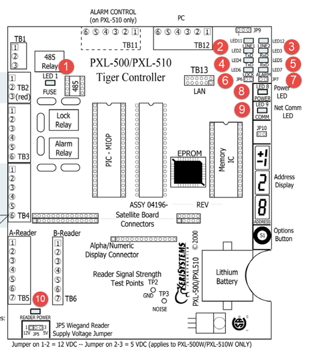
- LED 1 (Fuse LED) - Indicates if there is a power problem and if the thermal power fuse is open. In normal operation this LED should be off.
- LED 2 and LED 3 (TxD and RxD) - Both LEDs should be solid green when making a Serial connection.
- LED 4 and LED 5 - Not Used.
- LED 6 (Lock LED) - The lock LED will be solid green when the lock relay is active.
- LED 7 (Alarm LED) - The alarm LED will be solid green when the alarm relay is active.
- LED 8 (Power LED) - Indicates correct input power - LED will be solid green when the controller is receiving the correct voltage. It will be solid red if there is a power-problem.
- LED 9 (Comms LED) - Indicates when the controller has good RS-485 comms. The LED will be flashing green when the controller is communicating on the RS-485 network.
- LED 10 (Reader Voltage LED) - Indicates when the Wiegand reader output on a PXL-500W is set for 12VDC - LED is solid red when the Wiegand reader voltage is set to 12VDC
Related Articles
PXL-500 Hardware Installation Guide
1.0 Introduction This document contains installation guidelines and wiring diagrams for the installation of the PXL-500 Controller. Notes: A Serial connection is only supported when using the Doors.NET software. If using the PXL controller in ...PXL-500 Troubleshooting Guide
Following is a list of possible scenarios you may encounter when setting up or using the PXL-500 controllers. You will then see a possible solution or a list of possible solutions listed in order of the most likely cause: 1.0 Controller Communication ...PXL-500 Controller Factory Reset
1.0 PXL-500 Standard Controller RAM Reset If you're turning controller power on for the first time, or have just changed the EPROM/PIC, the PXL-500/PXL-510 controller RAM must be reset before performing any other action... this clears any spurious ...PXL-500G Vehicle Access Controller
PXL-500G Vehicle Access Data Sheet (Attached).PXL Elevator Control Using PXL or LC Controllers
1.0 Introduction PXL-500 controllers can be used for proximity elevator control applications. When using a PXL-500 with an SB-593 you will be provided with two floor increments of elevator control at an economical price. A single MS or Wiegand reader ...