PXL-500 Troubleshooting Guide
Following is a list of possible scenarios you may encounter when setting
up or using the PXL-500 controllers. You will then see a possible solution
or a list of possible solutions listed in order of the most likely
cause:
1.0 Controller Communication Issues
-
Cannot connect to the primary PXL controller - general
- If using Doors.NET, go to Setup >> Hardware Setup >> All, select the PXL gateway and verify it is online. If using Borealis, go to Hubs and ensure the PXL hub is online.
- If using Doors.NET and the system is an upgrade from Doors32, verify you have run the gateway wizard and have selected the PXL gateway.
- If using Doors.NET and the system is an upgrade from Doors32 (or if the controller is brand new), you should perform a factory reset on the primary controller (the controller addressed as #1).
- If using Doors.NET - check in the controller properties if comms is set to manual. If it is right-click the controller and select connect.
- If using Doors.NET - If you are using an older controller type (pre-2010) the controller is probably one of the older legacy controller types and will need to be enabled on your Doors.NET license.
- Ensure the controller is displaying a green power LED (LED8).
- With a Digital Volt Meter (DVM), ensure the controller is receiving between 12VDC and 14VDC on the TB2 power input connector.
- Press the white S1 button and ensure the address displayed is #1.
- Select the Primary controller in the hardware tree. In the controller properties, verify that the controller is enabled.
- Are transorbs installed across the locks to suppress any transients?
- Ensure the controller has a quality earth-ground connection.
- Ensure the controller is not installed next to known sources of electrical noise/interference... examples include electric vehicle charging stations, high-voltage power cables or switching power supplies. -
Cannot connect to a PXL via Serial connection (applies to
Doors.NET or Doors32)
- Ensure the JP6 and JP7 jumpers are across both sets of pins.
- Is the controller receiving the correct voltage? - (Between 12 and 14 VDC)?
- At the upper right corner of the controller PCB is a set of LEDs. Initiate a data transfer command and view these TxD and RxD LEDs. These LEDs should flicker if data is being transferred to and from the controller.
- Verify the communication cable is properly connected.
- If using a direct serial cable ensure it is wired correctly.
- Is the COM port number correctly defined in the Doors.NET communications channel which is assigned to the controller?
- Is the total cable run length less that the recommended 15 meters/45 feet? -
Cannot Connect Via USB-Serial Adapter (applies to
Doors.NET or Doors32)
- Are jumpers JP6 and JP7 are across both sets of pins?
- At the upper right corner of the controller PCB is a set of LEDs. Initiate a data transfer command and view these TxD and RxD LEDs. These LEDs should flicker if data is being transferred to and from the controller.
- Is the USB-Serial adapter on Keri's recommended peripherals list?
- Is the adapter correctly installed? and displaying in Device Manager of the host PC.
- If the adapter is showing in Device Manager is the assigned COM port number displaying?
- Is the assigned COM port number correctly defined in the Doors.NET communications channel which is assigned to the controller?
- Does the USB cable length exceed 10 metres?
- Does the serial cable run length exceed 15 meters/45 feet? -
Cannot connect via Ethernet connection
- Ensure the JP6 and JP7 jumpers are OFF both the sets of pins - This configures the controller to communicate with the LAN-520 plug-on module.
- If it is a new controller, has it been RAM reset? - If the system has been upgraded from Doors32 has the Primary controller had a RAM reset?
- Is the controller receiving the correct voltage? - (between 12 and 14 VDC)?
- Verify the LAN-520 is correctly connected to the PXL controller. On the LAN-520 module you should be seeing 2 x green LEDs and 1 x amber LED. If you can see a red LED then the LAN-520 either has a fault, it is in programming mode, or there is an IP conflict on the network.
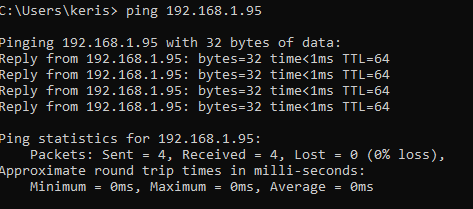
- Verify you can successfully ping the IP address of the LAN-520.
- In the Doors.NET controller settings ensure the port # is set as 10001.
- Telnet into the LAN-520 and ensure the channel 1 port # is also 10001.
(Telnet [IP ADDRESS] 10001 - If connection is successful, a blinking curser will be displayed in the command prompt and the green link LED on the LAN-520 will be blinking on and off. If this does not connect over port 10001 then you won't be able to connect using Doors32/Doors.NET.
- Is there a firewall or managed switch that could be blocking the communication port numbers? (10001 or 10021).
- Is the Network communication channel enabled?
- Check the PXL firmware - LAN-520 only works with PXL firmware version 8.4.30 or later.
-
Cannot Connect to a Secondary PXL Controller
- Is the small, black TB1 network connector correctly inserted at the controller?- Is the controller's com LED (LED 9) flickering?- Is the controllers correctly address (press the small, white S1 button to find out the controllers address).- Have the correct terminal connectors been used. You should not use old connectors with newer controllers.- Is the PXL network wired as a continuous multi-drop daisy-chain between Secondary controllers or are there multiple spurs connecting to the Primary PXL?- If there are multiple spurs and multiple Secondary controllers offline it can be helpful to test communications on a single spur at a time.- If the controller is a legacy PXL has the legacy count been enabled on your license key?Check the RS-485 line continuity.
-
Network Update Fails on PXL Secondary Controllers
- If you are setting up a new system or if the Primary PXL has had a factory reset then the initial network update will fail on the Secondary PXL controllers. To correct this you should perform an auto-config - this will re-configure the Primary PXL with its internal list of Secondary controllers. A network update following the auto-config will then succeed.
- You should also ensure the controller model is correct. For example; if an SB-593 (satellite board) has been added to a controller this change will need to be confirmed in the Doors.NET software. If using Borealis, the controller model will need to be set correctly in the controller settings.
- In Live Events the controller is generating 'Controller Self-Test Failure' events
- If you are seeing this event then it is most likely that the controller's 3v lithium backup battery is flat and needs to be replaced. To replace the battery, the controller should be down-powered. Once the battery has been replaced, powered-up and comes back online you should perform an update from the software (by selecting the controller and clicking the 'Update Network' icon).
-
The PXL controller does not power-up - the power LED (LED8) is off
- Check the main power circuit breaker.- Verify the positive power lead is on TB-2, pin 1 and the negative power lead is on TB-2, pin 2 (negative). The incoming voltage should be between 12 and 14 volts.- Disconnect the power supply from the controller and verify the supply's voltage. The voltage outputted by the power supply should be between 12 and 14 VDC.- Remove the LCD-1 display if there is one connected - It may be bad or incorrectly plugged in.- Remove the SB-593 if there is one - It may be bad or incorrectly plugged in.
-
The PXL power LED (LED8) is red and the address display is flickering various numbers
- If the supply voltage detected by the controller falls below 11.1VDC or is higher than 14.4VDC, the power LED8 goes red and the detected input voltage value is displayed on the controller's display - if there is a battery backup on the power supply disconnected that and check it is charging correctly.
- Try disconnecting the lock(s) as there may be a faulty lock which is dragging down the power supply voltage.
-
The FUSE LED (LED1) is red
- CAUTION: The fuse becomes hot over time and may burn. Always give the fuse time to cool before touching.If the fuse LED1 is red, the fuse is open because the power and ground lines are reversed. Turn controller power off and verify the polarity of the power coming to the controller.
-
The FUSE LED (LED1) is Green
- CAUTION: The fuse becomes hot over time and may burn. Always give the fuse time to cool before touching.If the fuse LED1 is green, the controller’s fuse has opened because there is a power problem. Remove power from the unit and give time for the fuse to cool, then verify the polarity of the power coming into the controller. Measure the input voltage across pin 1 (positive) and pin 2 (negative) of TB-2. The voltage should read 12 and 14 VDC. If the controller's power is correct the controller needs to be serviced.
2.0 Reader Issues
-
The reader does not beep and/or reader LED does not flash when a card is presented
- Verify the wiring to the reader from the TB5 and TB6 connectors is correct.- Ensure the reader wire connections have been made on lead wire and not wire insulation.- Measure the voltage as close to the reader head as possible. The voltage at the reader should be between 12 and 14 VDC.- The controller might be receiving transients - Check that transorbs have been installed across the locking devices.- See if the reader starts working if the reader is disconnected and plugged back in.- If using Wiegand readers, verify that the reader is receiving the correct voltage. The JP5 jumper in the lower left corner of the PXL-500W allows you to supply either 5 or 12VDC to the reader.- Check if the controller is mounted too close to a source of EMI. There should be at least 4 feet separation between the controller and the power supply. Also, verify there are no other EMI sources (such as a computer monitor) in close proximity to the controller.- Check that the correct type of card is being presented to the reader.- The card may be faulty so try presenting a different card or try that same card at a different reader.
-
The Reader LED is Off
- Check that the PXL controller is powered-up.- Verify the wiring to the reader from the TB5 and TB6 connectors is correct.- Ensure that the correct controller type is being used (PXL-500W for Wiegand readers and PXL-500P for Keri MS-series readers).
-
The Reader's Read-Range is Very Short
- Verify pin 3 of the TB2 connector is connected to a good earth ground.- Check that the reader is not mounted too close to an EMI source.- Verify that the reader's cable is properly shielded and not too close to an EMI source.- If the reader is mounted on metal ensure it is a reader that is designed to be mounted on metal.
-
At Power-Up the Reader Continuously Beeps
- Check that the door contact input is not open (n/c contact across pins 1 and 2 of TB4) - If a door switch is not being used ensure there is a jumper across these two pins.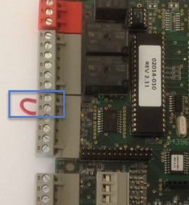
- The controller's ram may be corrupted or the controller may not have been ram reset when it was first installed. Follow the PXL ram reset procedure to revert the controller to its factory settings.
- Check the voltage going to the reader (take the voltage reading as close to the reader head as possible) - it should be between 12VDC and 14VDC.
Note: Following a ram reset all the access control data will be cleared so it is important to check the controller is online in the software and the database in the software is up to date.
- The Door is Locked but the Reader's LED is Green
- When using Farpointe Wiegand readers (in single-line LED mode) the reader LED will be green if the controller is factory reset. It will be displaying amber following the first successful update. -
The Doors Does Not Unlock From the Software
- Check that the controller is online.- Check if there is an update in progress. You will not be able to command the doors from the software while an update is in progress.
3.0 Cardholder Access Issues
-
Cards That Were Getting Access are now Getting Access Denied
- If none of the cards are working then it is a good idea to ram reset the controller. The comms issue can happen if power is lost to the controller when the software is communicating with it.
- If the cards stopped working after the power was lost at the controller then it is likely the 3v lithium coin cell battery is dead. Down-power the controller, remove the battery and take a voltage reading of it - It should be at 3 volts or very nearly 3 volts (the PXL backup battery is a CR2325).
- Verify the controller is receiving correct voltage (between 12 and 14VDC).
- If the PXL controller randomly loses all the card information but the on-board lithium battery is at correct voltage then there may be poor grounding on the site, or some kind of transient surge may have got onto the RS-485 line.
-
Cardholder is Incorrectly Gaining Access
- If doors have been removed from or added to an access group, then the controller network will need to be updated. An update network required indicator will be displayed in the admin client.
Related Articles
PXL-500 Troubleshooting and Diagnostics - P/N: 01917-001 Rev. A
PXL-500 Troubleshooting and Diagnostics GuidePXL-500 Setup in Doors.NET With a USB-Serial Adapter
1.0 Introduction This guide explains how to setup a connection to a PXL-500 Primary controller using a USB-serial adapter. The adapter used in this example is the Keyspan 19-HS by TRIPP-LITE which is one that Keri highly recommends. It is robust, ...PXL-500 Hardware Installation Guide
1.0 Introduction This document contains installation guidelines and wiring diagrams for the installation of the PXL-500 Controller. Notes: A Serial connection is only supported when using the Doors.NET software. If using the PXL controller in ...PXL-500 Controller Offline Flowchart
This flowchart is aimed at helping installers to troubleshooting an offline PXL-500 controller network.PXL-500 - Upgrade Advisor
This article explains how to use the new version of the PXL Upgrade Advisor. 1.0 Download the New Upgrade Advisor from here: Save the entire zip file to a specific folder on the host PC. 2.0 Extract the Contents of the ZIP File Navigate to the folder ...