Single Door Module (SDM) MR51 Setup
Single Door Module (SCP-SDM) Setup in Doors.NET
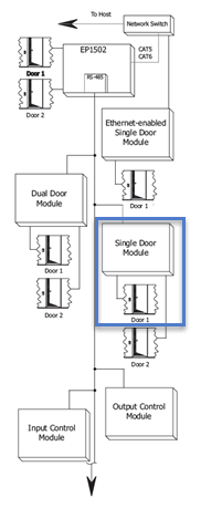
The SCP-SDM (Single Door Module) has all the I/O needed for controlling a single door. Each SDM will interface one card reader, two general purpose input monitor points and two control relays to provide access control and security monitoring through an intelligent controller. The Reader Interface provides a solution for interfacing to a TTL/Wiegand type reader. The Reader Interface can accept data from a reader with clock/data or Wiegand signaling, provides a tri-state LED control and buzzer control. Twp form-C relay outputs may be used for strike control or alarm signaling. Two supervised inputs are provided for monitoring the door contact and exit push button. Communication to the interface is accomplished via a 2-wire RS-485 interface.
Power to the Module
The interface requires 12Vdc ±15%. The power source must be filtered. DO NOT use AC transformers directly to power the interface. The 12Vdc is passed to the telco modular jack and is available for powering a reader.
Communication Wiring
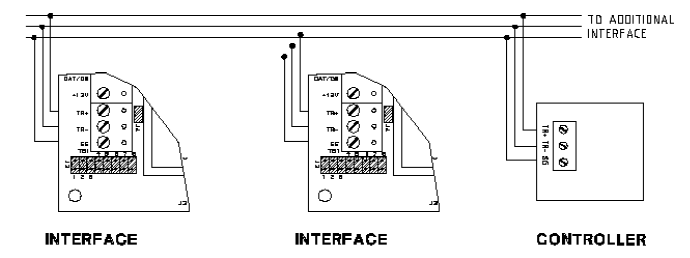
The Interface communicates to a controller via a half duplex multi-drop RS-485 interface. The total cable length is limited to 4,000 feet (1,200 meters). Shielded cable of 24AWG with characteristic impedance of 120 ohm is specified for the RS-485 interface. The last devices on both end of the cable should have the termination installed (set jumper J4 on).
J2 Jumper Settings
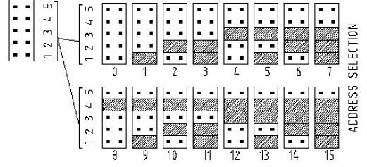
Each SDM must be configured with a unique address and correct baud rate using the J2 jumpers. There are 8 jumpers in total. The first 5 are used to set the device address.
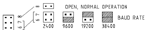
Jumpers 6 and 7 are used to set the communication baud rate. By default all SCP hardware is configured to communicate using 38,400 baud rate.
(The two black dots indicate that the jumper is NOT installed across both pins).
Typical Setup Procedure
- Set the correct address for the SDM using jumpers 1-5 of J2.
- Set the correct baud rate using jumpers 6 and 7 of J2 (jumper 8 is not used).
- If the SDM will be the last module on the RS-485 network, ensure a jumper is across both pins of J4. This will engage the 120 OHM line terminating resistor.
- Connect the RS-485 network on the TB1 connector.
- Apply power to the SDM on the TB2 connector.
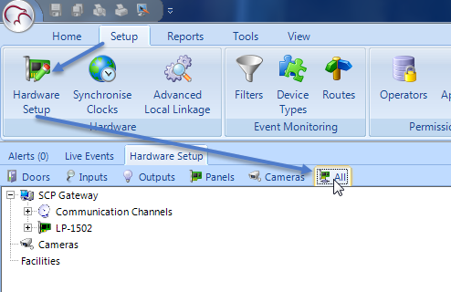
- In the Doors.NET software, click on Setup >> Hardware Setup >> All.
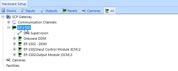
- Double-click the SPM (System Processor Module) in this case an EP-1502. You will see displayed in the hardware tree all devices that are already added to the SPM.
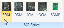
- With the SPM (EP-1502) highlighted, click the SDM icon from the SCP Series hardware selection ribbon.
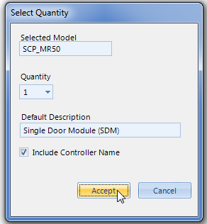
- A dialog box will appear, giving you the option to add multiple SDM modules and to change the default description.
- Click Accept and the SDM module will immediately be added to the hardware tree.
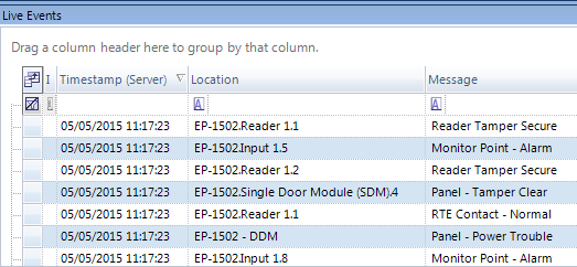
- If the SDM is configured correctly you should see events appear from the OCM in the Live Events grid.
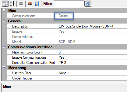
- Highlight the SDM in the hardware tree and in the properties it should show as online.
Related Articles
Dual Door Module (DDM) MR52 Setup
SCP MR52/DDM Setup Power Supply to the MR52-S3 The MR52-S3 accepts either 12Vdc or 12Vac for power. Locate the power source as closed to the interface as possible. Make power connection with minimum of 18AWG wires. The input voltage is filtered and ...NXT 4x4 Module Setup
Basic NXT 4x4 Setup and Configuration 1.0 Using Standard NXT Controllers The NXT 4x4 module is added to standard NXT controllers using Auto-configuration. The 4x4 module is connected to the controller via one of the available RS-485 ports (these are ...MR16IN - Input Control Module Setup
SCP-MR16IN-S3 (Input Control Module) Setup The Input Control Module (MR16IN-S3) processor provides sensor interface and output controls for security/ access control and other applications. The controller has 16 input channels for supervised contact ...Setup a PXL-500 Controller
1.0 Introduction IMPORTANT NOTE: The PXL and Entraguard controller types are not supported with Doors.NET version 6 (v6.0.0) and future versions. Ongoing support and development for these products will be in Borealis. Doors.NET v5.4.0.8 was the last ...Setup Access Groups
1.0 Introduction Access groups are setup in Doors.NET via Home >> Access Groups. There are two default access groups; Never and Total Access. When a controller is added to the system it's doors are automatically added to the Total access group (with ...