Setup Area Control
1.0 Introduction
Area Control is a licensed feature that is supported with the NXT Mercury Powered (MSC) and Mercury (SCP) controllers. The main functions of Area Control is to combined it with Local Linkage to:
- Restrict how many people can enter a certain area of a facility
- To ensure there are a certain a certain number of cardholders in a certain area
- Or to automate the activation or deactivation of something; such as turning on some office lights when someone enters then automatically switching off those lights when the last cardholder leaves.
Note: For this application, a reader is required for entering the area and a second reader is required for exiting the same area. If the readers are on either side of the same door then the readers need to be paired in the software, or one of the readers must be an Exit reader - (Exit readers are only available for the NXT reader technology).
Note: This feature is only available with Mercury or NXT Mercury-Powered controllers.
2.0 Using Area Control and Local Linkage to Control Lights
Some facilities are given environmental 'green points' for efficient use of electricity. One way this can be achieved is by switching on lights only when a room is in use. Setting this up requires Area Control and Local Linkage licensed features. In practice, the principle is someone enters a defined area and some lights will automatically switch on and when the last person leaves the area, the lights will automatically be switched off.
2.1 Area and Reader Setup
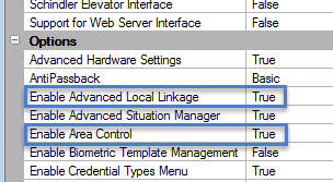
- Ensure both Area Control and Local Linkage are enabled in your license. Open the License Manager, click on the license tab and check that both these features are set to True.
- Go to Setup >> Hardware Setup >> All.
- Highlight the controller that will be used for this application.
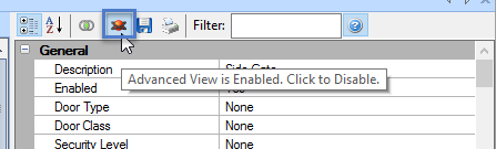
- Ensure that Advanced View is enabled for the controller properties.
- Scroll down the properties list and locate 'Enable Area Control' - Set this to True then save.
- You will immediately see a node appear beneath the controller; it is named 'Area Control'.
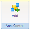
- Highlight this node then click the Add Icon from the ribbon bar to add a new area for the controller.
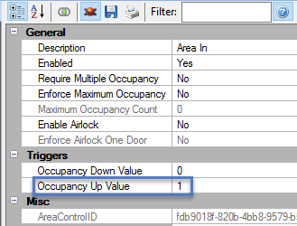
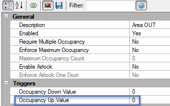
- Highlight this new area and name it Area IN or something very similar.
- This area is automatically enabled but you have to set the Occupancy Up value to 1. This will cause an event to be generated when someone presents their card to enter the area. This occupancy up value is only applied to the IN area.
- Click save once you have made these changes.
- Highlight the Area Control node again and click the Add icon once more to add a second Area.
- Name this area Area OUT then save. You do not need to set any up values or down values to this area.
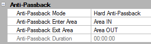
- Highlight the Entry reader connected to the controller, in the reader properties locate the Anti-Passback section.
- Set the the Anti-Passback Mode to Hard, set the Enter Area to Area IN and the Exit Area to Area OUT.
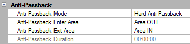
- Highlight the Exit reader connected to a different bus of the same controller and again locate the Anti-Passback section.
- Set the Anti-Passback Mode to Hard but set the Enter Area as OUT and the Exit Area as IN (the opposite to what you have set on the Entry reader).
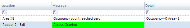
- If you now present a valid card to the Entry reader you will get access granted plus additional occupancy events:
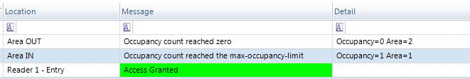
- When you present a card to the Exit reader you will get access granted and a different occupancy event; these events will be used as triggers to switch on and off the lights within the area.
2.2 Local Linkage Procedure Setup
- The Local Linkage feature is now used to define what we want to happen (switch on and off the lights) and when we want this to happen (when someone enters or exits the area).
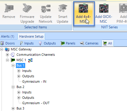
- First, ensure you have an NXT-4x4 module connected and online to the controller. One 4x4 module will allow you to control 4 different sets of lights as there are 4 general purpose outputs on each 4x4 module. For this example we will just use one 4x4 module.
- Highlight one of the controller's buses and add the 4x4.
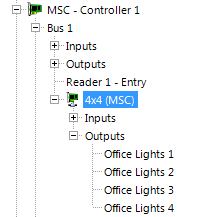
- When the 4x4 appears in the hardware tree, expand the outputs and re-name them (and save).
- Next, from the Setup tab click on Advanced Local Linkage.

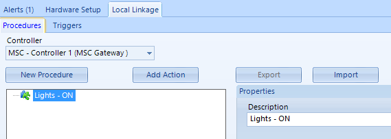
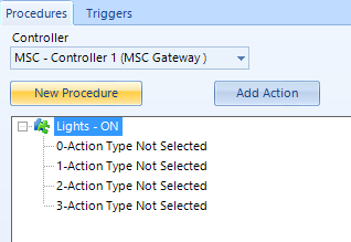
- Select the relevant NXT Mercury Powered controller from the controller list then click New Procedure.
- The first procedure to setup will switch on the lights so rename the procedure accordingly (then save).
- Click the Add Action button four times and 4 action types will appear.
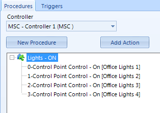
- Each action will activate one of the outputs on the 4x4 module so starting with the first action; select Control Point Control from the Action Type drop-down list, select the first control point on the 4x4 (renamed a few steps earlier) and set it to On.
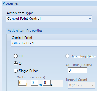
- Repeat these steps for each of the 4 control points on the NXT 4x4.
- A second Procedure now needs to be added and again it will include 4 actions. This time the actions will be to de-activate the control points.
- Click New Procedure again, re-name it and then click Add Action 4 times once again.
- The second procedure will de-activate the control points when executed so this time set each of the 4 control points to Off.
- You can now test that each of the procedures functions correctly...
- Right-click the first procedure select Execute and all 4 control points should activate on the 4x4.
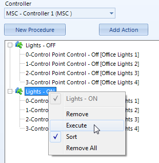
- Right-click and execute the second procedure and the same control points (outputs) should then de-activate.
2.3 Local Linkage Trigger Setup
- When the procedures are executing correctly click on the Triggers tab and then click the Add Trigger button.
- Rename the trigger 'Access - IN' or something similar.
- From Execute This Procedure select the procedure to switch on the lights.
- Procedure command remains at the default value.
- Source Type needs to be set to Access Area.
- From Transactions on the right, select 'Occupancy Count Reached Maximum limit'.
- From Source select 'Area IN'.
- Activate During This Schedule should be set to Always, or you can of course restrict when this feature works by selecting an alternative Time Schedule.
- The last setting; Trigger Variable Logic remains at the default setting.
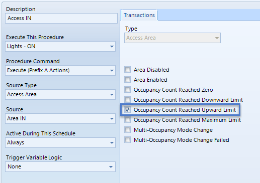
- Finally, save the trigger.
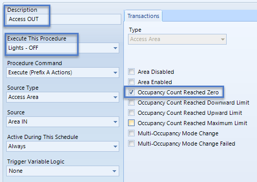
- A second trigger now has to be created. It is very much the same as the first trigger except; the description will be different, the procedure to execute will be to switch off the lights and the transaction type will be 'Occupancy Count Reached Zero'. All the other settings will be the same.
- The trigger setup is now be complete: When you get access granted at the Entry reader the 4 outputs on the 4x4 should activate and when you get access on the Exit reader the outputs should de-activate.
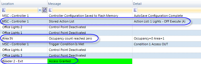
- Because the trigger to switch off the lights is when occupancy reaches zero multiple people can enter the area and the lights will only go off when the last person exits.
Contact Keri Systems technical support for additional information about other system applications using Area Control & Occupancy Counting or Local Linkage.
Related Articles
Setup an Airlock
1.0 Introduction The airlock feature is available on NXT-MSC or Mercury SCP controller when Area Control is enabled on the license. This is so you can setup two or more areas as 'airlock' areas. Anti-passback is not required for airlocks to work, ...EP4502 Controller Setup Guide
1.0 Introduction The setup for the EP-4502 controller is very much the same as the EP-1502 and EP-2500. All EP controllers are pre-configured for use on a network, therefore additional TCP/IP configuration must take place in the field prior to ...EP1501 Controller Setup
1.0 Introduction The LP1501 is an edge-capable intelligent controller that is expandable up to 8 downstream serial input/output modules and up to 16 MR62e network ready door controllers (for a total of 17 doors/openings). The feature-rich LP1501 ...MP2500 Controller Setup
1.0 Introduction The MP2500 is a powerful, intelligent controller that's network-enabled and is scalable to 64 doors/openings with the addition of downstream door modules. The high performance MP2500 system processor module uses an Ethernet ...EP2500 Controller Setup
1.0 Introduction The EP2500 is a powerful, intelligent controller that's network-enabled and is scalable to 64 doors/openings with the addition of downstream door modules. The high performance EP2500 system processor module uses an Ethernet ...