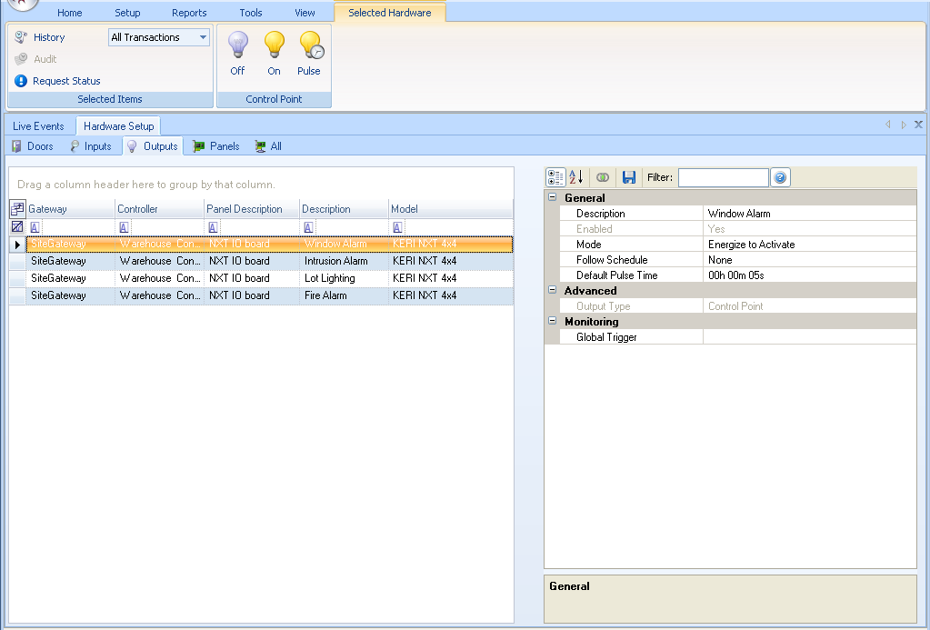
Setup Outputs
1.0 Via the Outputs tab

2.0 Via the Hardware Tree
- You can also go to Setup >> Hardware Setup >> All to display the hardware tree.
- Double-click a controller to view the controller's buses.
- Double-click the controller bus to locate the inputs and the outputs.
- If you have an input/output or I/O module added to the controller's bus you can double-click outputs to view a list all of the outputs available on the module.
3.0 Display Output Information by Column
The left pane of the grid lists all recognized Outputs in alphabetical order, prioritized by column. Drag column headers above the header field to filter and display information per your specific needs and priorities. Select a output listed in the left pane and all its configuration parameters are displayed in the right pane.
Information displayed in sortable columns:
- Gateway - the gateway type/name for the controller to which the output is connected.
- Controller - the name assigned to the controller.
- Panel Description - the type of controller panel (by manufacturer and physical characteristics).
- Description - the names assigned to the individual outputs on that controller.
- Model - the type of device providing output.
4.0 Review/Edit Input Configuration Parameters
The right pane of the grid lists all information and configuration parameters for the output selected in the left pane. If an item in the grid is grayed-out it is not changeable.
General
- Description - enter a descriptive name for this input (128 characters max)
- Enabled - enable or disable this input
- Mode - output is active-energized or active-deenergized
- Follow Schedule - assign this input a time schedule during which it is active
- Default Pulse Time - the amount of time an output pulsed when active; up to a maximum of 18 hours, 12 minutes, 15 seconds
Advanced
- Output Type - identify the type of output, typically a control point; other output types may have additional configuration parameters that need to be set
Monitoring
- Global Trigger - select an event trigger that will be tested when this output creates an event - if the event matches the trigger, the trigger will activate.
5.0 Selected Hardware Output Operations
The Selected Hardware tab displays two operation groups with manual operation commands that can be applied to selected inputs in the grid.
Note: As is typical with Windows based programs, you can select multiple, random outputs or consecutive sets of outputs using the standard Windows Ctrl-Click and Shift-Click commands.

Selected Items
- History - list an event history for selected outputs; the pull-down menu beside the History option allows you to select a specific event on which to display output history.
- Audit - list the changes made to and operations performed on selected outputs.
- Request Status - returns operational status for the output and the controller to which it is connected; the status is displayed in the Quick-Open Status tab at the bottom of the program window.
Control Point
- Off - manually turn the output OFF
- On - manually turn the output ON
- Pulse - manually pulse the output per the pulse time
 Note: A quick way to apply manual output operations is to select your outputs in the grid and click the right-button on your mouse. A context menu with pull-down options appears allowing you to quickly and easily perform these operations.
Related Articles
NXT 4x4 Module Setup
Basic NXT 4x4 Setup and Configuration 1.0 Using Standard NXT Controllers The NXT 4x4 module is added to standard NXT controllers using Auto-configuration. The 4x4 module is connected to the controller via one of the available RS-485 ports (these are ...Setup Area Control
1.0 Introduction Area Control is a licensed feature that is supported with the NXT Mercury Powered (MSC) and Mercury (SCP) controllers. The main functions of Area Control is to combined it with Local Linkage to: Restrict how many people can enter a ...MP2500 Controller Setup
1.0 Introduction The MP2500 is a powerful intelligent controller with native network support and is scalable to 64 doors/openings. Built on the Authentic Mercury platform, the intelligent controller uses an on-board Ethernet port to connect to cloud ...MP1502 Controller Setup
1.0 Introduction The MP1502 provides a two-door interface with auxiliary I/O, including onboard I/O for 2 readers, 8 supervised inputs and 4 relay outputs. In addition to centralized biometric template management, the controllers support a wide range ...EP1502 Controller Setup
1.0 Introduction The EP1502 provides a two-door interface with auxiliary I/O, including onboard I/O for 2 readers, 8 supervised inputs and 4 relay outputs. In addition to centralized biometric template management, the controllers support a wide range ...