Simons Voss Lock Integration - Quick Start Guide
1.0 Introduction
1.0 Introduction
Doors.NET interfaces directly with the Simons Voss range of wireless locking devices. Communication to the locks is via Wi-Fi using a Gateway Node. The integration provides you with a real-time, online system.
Programming tasks performed in Doors.NET are sent out to the locks automatically (via the Gateway Node). This eliminates the need for a configuration reader and there is also no need to physically visit the locks to perform any manual updates.
The integration allows you to: remotely lock and unlock doors, generate live events in real-time, retrieve hardware status information and notifications (such as low-battery events or locks going offline). New cardholders and cardholder changes are automatically updated at the locks and locks can be configured to automatically lock and unlock (by assigning auto-unlock schedules).
Note:
- Effective from Doors.NET v5.2.0 there is a slight difference in setting up the Gateway Node. Prior to v5.2.0, a gateway node would be added to a controller bus. From v5.2.0 and onwards, the gateway node is added to the hardware tree as a Network Device. This change improves the setup workflow of wireless lock integration with NXT-MSC and Mercury controllers. Although a controller is still required for the integration, this change also allows for all of the controller buses to be used for general access control.
- The integration only covers the integration setup in Doors.NET and does not cover any of the initial setup using Smart Intego.
2.0 Smart Intego Devices Config File
IMPORTANT NOTE: This setup guide assumes you have an existing, detailed understanding of how to setup and configure the locks using the Simons Voss Smart Intego software. The Smart Intego software is covered in a separate training session. Smart Intego is used to capture the gateway node, capture and configure the locks and pair them with the Gateway Node. Smart Intego is also used to create and export the hardware config file which is required for initially setting up the integration.
Note: If you are using multiple gateways these will all be included in the same config file.
Before adding the Simons Voss hardware to Doors.NET, it must already be setup and configured correctly using Smart Intego.
This guide explains how to quickly and easily add the Gateway Node and the locking devices (cylinders, lock handles, etc) to Doors.NET.
3.0 System Capacities
- The maximum number of locks per gateway is 16
- The maximum number of gateways per controller is 8
4.0 Licensing Requirements
Simons Voss integration is a licensed feature and therefore will need to be enabled on your Doors.NET license. Your Doors.NET license should be enabled for the number of Simons Voss devices you will be adding to the Doors.NET software.
Once the feature has been enabled, perform the following steps:
- From Windows Start Menu, go to Doors.NET >> License Manager.
- Right-click License Manager and select 'Run as Administrator'.
- Select Application Server from the list on the left.
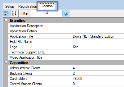
- Click the License tab.
- Click the ACTIVATE button at the bottom of the window.
- You should see a registration successful notification. Click OK.
- Confirm a restart of the application server.
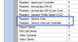
- Scroll down the list of license capacities and locate Readers - Simons Voss and Readers - Simons Voss per Controller. These should match the number of Simons Voss devices you will be adding.
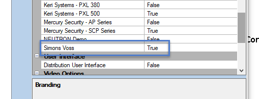
- The Simons Voss hardware type will also show as enabled.
- Each controller can support a maximum of 8 gateway nodes and each gateway node can support a maximum of 16 locks.
5.0 Export the Hardware Config File
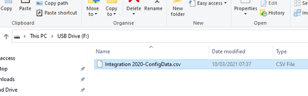
The Smart Intego software gives you the ability to create an exported file of all the lock information (the lock name, chip ID,). This exported file can then be imported into Doors.NET as a very quick and simple method of adding the locks. This also ensures the lock are added to Doors.NET in the correct order. If the Doors.NET software will reside on a different PC/host workstation then you should copy the exported file onto a portable storage device to transfer the config file across.
- From within the Smart Intego software, ensure you have paired all the locks/devices with the gateway.
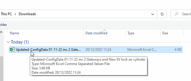
- Click on File >> Export Configuration Data.
- Save the config file to somewhere on the PC (or onto a storage drive if the host PC will be on another workstation).
- Smart Intego will notify you of how many locks/devices have been exported to the .CSV file.
6.0 Add the Gateway Node to Doors.NET
6.1 Setup Using NXT-MSC Controllers
This section assumes you already have an online NXT Mercury-Powered (MSC) controller.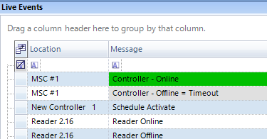
- Log into Doors.NET (default username and password are both admin).
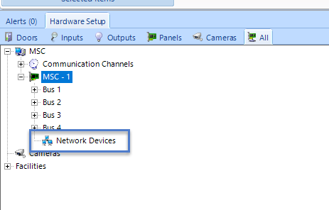
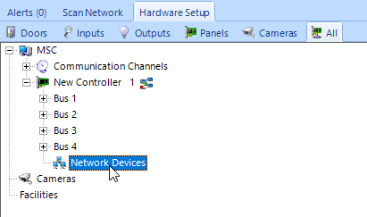
- Go to Setup >> Hardware Setup >> All to display the hardware tree.
- Double-click the controller that the gateway node will be added to.
- Select Network Devices (located beneath the controller buses).
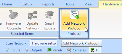
- Click Add Network Protocol icon from the ribbon bar.
- Expand the network devices node and you will see a new entry named 'Undefined'. Select this new entry and the properties will be displayed on the right.
- Use the Protocol (Network) drop-down menu to select Simons Voss.
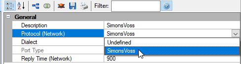
- Save the network protocol properties.
- You will be prompted to reset the controller. Click YES to go ahead with the reset.
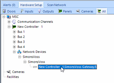
- The Simons Voss network protocol will now appear beneath Network Devices.
- Select the newly added Simons Voss protocol.
- From the ribbon bar, click on the Add Simons Voss Gateway icon.
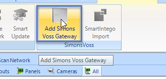
- A dialog box will appear, giving you the option of adding multiple gateways, changing the default description and you can also choose to include the controller name in the gateway description. Click the ACCEPT button to go ahead with importing the gateway.
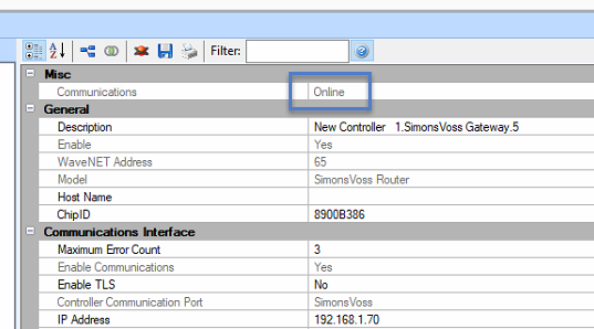
- The gateway will be added to the hardware tree but if you select the gateway you will see that there is configuration data missing.
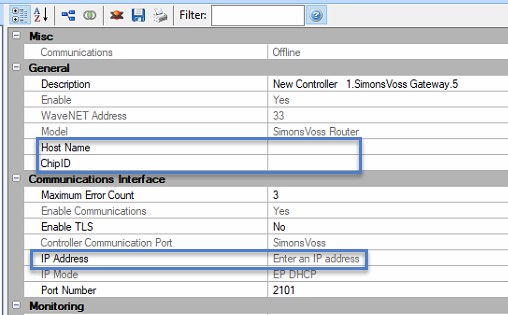
The gateway configuration (for example; the programmed IP address) is contained in a config file, which is imported into Doors.NET - See section 7.0).
6.2 Setup Using Mercury Controllers
Effective from Doors.NET v5.2.0, the Simons Voss integration is also available when using Mercury EP or LP series controllers. This section assumes you already have an EP or LP series controller added to Doors.NET and online.
- From within Doors.NET, go to Setup >> Hardware Setup >> All.
- The hardware tree will appear.
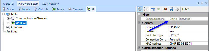
- Select the Mercury controller and in the controller properties, ensure the controller is online.
- Double-click the controller to view the controller attributes.
- Select Network Devices.
- Click the ADD NETWORK PROTOCOL icon.
- Expand the network devices node and you will see a new entry named 'Undefined'. Select this new entry and the properties will be displayed on the right.
- Use the Protocol (Network) drop-down menu to select Simons Voss.
- The other protocol settings can be left at their defaults.
- Save the network protocol properties.
- You will be prompted to reset the Mercury controller. Click YES to go ahead with the reset.
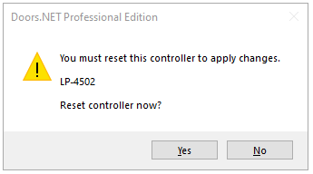
- The Simons Voss network protocol will now appear beneath Network Devices.
- Select the newly added Simons Voss protocol.
- From the ribbon bar, click on the Add Simons Voss Gateway icon.
- A dialog box will appear, giving you the option of adding multiple gateways, changing the default description and you can also choose to include the controller name in the gateway description. Click the ACCEPT button to go ahead with importing the gateway.
- The gateway will be added to the hardware tree but if you select the gateway you will see that there is configuration data missing.
The gateway configuration (for example; the programmed IP address) is contained in a config file, which is imported into Doors.NET - See next section).
7.0 Import the Hardware Config File
To save you having to manually add the locks into Doors.NET, you can import the lock config file which also eliminates the possibility of the locks being added in an incorrect order. The following steps also eliminate the need to configure the gateway communication settings.
Notes:
- The locks will already need to be communicating with the gateway node (configured using the Smart Intego software).
- The hardware config file contains all the gateways and locks for your site (it is not one config file per gateway). However, you do have to manually add each of the gateway nodes into Doors.NET.
The following steps explain how to import the gateway and locks config file.
- From within Doors.NET, open the hardware tree (Setup >> Hardware Setup >> All).
- Select the Simons Voss gateway node (added in the previous section).
- The Smart Intego Import wizard will appear. Click NEXT to proceed.
- Click the IMPORT button.
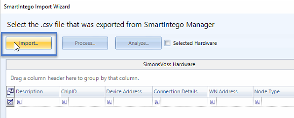
- Navigate to the location on the PC where the config file is located.
- Select the config file and click OPEN.
- Click the PROCESS button and a list will appear of all the devices in the config file.
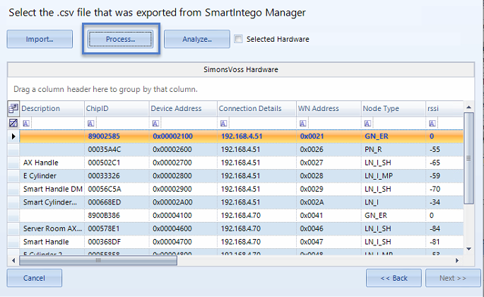
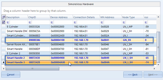
- Place a check mark in the Selected Hardware option - this will allow you to make multiple hardware selections.
- Select a gateway node (node type is GN_ER), then use the CTRL keyboard button to select the locks that have been added to that selected gateway (you will know which locks are added to the gateway because they will be displaying the same IP address in the connection details field.
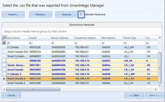
- Click the ANALYSE button.
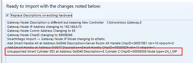
- A summary of the lock information will be displayed. If everything appears to be correct, click on the PROCESS CHANGES button. If PROCESS CHANGES is grayed-out then it is likely you are attempting to import an unsupported device. In which case you would need to click BACK and then de-select the unsupported device.
- The detected number of locks will be displayed in a dialog box and the locks will then be added to the hardware tree.
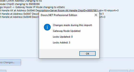
- Click okay and close the config file import wizard.
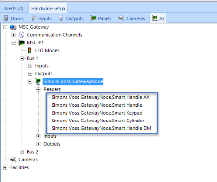
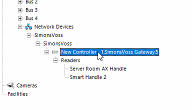
- The gateway will now be configured and the locks will be located beneath the gateway in the hardware tree.
- If you select the gateway node, in the gateway properties, you should see that it is online.
- In live events you should also see events that have been generated from the locks.
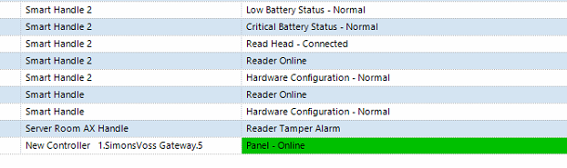
- After a few seconds each of the locks that are paired with the gateway, will come online.
8.0 Add a New Cylinder Lock or Smart Handle
Important Note: When adding additional locks to the system, you must first add the lock to the gateway using the Smart Intego software and then export a new (.csv) config file (which will be imported into Doors.NET).
- From within Doors.NET go to the hardware tree (Setup >> Hardware Setup >> All).
- Select the Simons Voss Gateway Node.
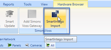
- Click the Smart Intego Import icon from the ribbon bar.
- The config import wizard will appear.
- Click NEXT.
- Click the IMPORT button.
- Select the updated config file.
- Click OPEN.
- Click PROCESS and all devices in the config file will be displayed.
- Again, ensure there is a checkmark in the Selected Hardware option.
- Use the keyboard CTRL button to select the existing gateway and then select the new lock which has been added to the gateway (or multiple additional locks).
- Click the ANALYSE button and you will see a summary of the lock(s) that will be added.
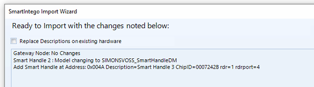
- Click the PROCESS CHANGES button.
- Close the lock added notification and close the import wizard.
- The new lock will now appear on the hardware tree.
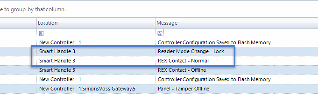
- A few seconds later you will see events from the new lock being displayed in live events.
9.0 Edit Lock Settings in Doors.NET
When you select a lock in the Doors.NET software, the lock properties will display on the right.
Note: Any setting which is grayed-out is non-editable.
- Description - Allows you to change the name of the lock.
- Enabled - Allows you to manually enable and disable the lock.
- Door Type - Allows you to set a specific door type to the lock (used for reporting purposes).
- Door Class - Allows you to set a specific door class to the lock (used for reporting purposes).
- CHIP ID - Displays the programmed CHIP ID for the lock.
- Auto Unlock Schedule - Allows you to select a schedule to determine when the lock will automatically lock and unlock during the day.
- Enable Door Contact - Enable and disable the door contact input (only available on the Smart Handle DM) lockset.
- Strike Timing - Minimum - Allows you to adjust the minimum strike time for the lock (unlock time following a valid card read.
- Strike Timing - Maximum - Allows you to adjust the maximum strike time for the lock (unlock time following a valid card read).
- Anti Passback Mode - Allows you to enable Antipassback on the lockset.
- Filter Door Change of State Transactions - Filters out the diagnostic messages from the door contact.
- Enrollment Reader - Allows you to configure the reader as an enrollment reader.
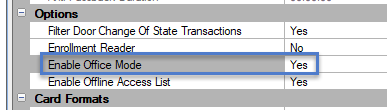
- Enable Office Mode - Enables Office Mode for the lockset.
- Enable Office Mode - Enable Offline Access List for the lockset.
10.0 Lock and Unlock from Doors.NET
The locks can be instantly controlled from the Doors.NET software - either from the doors grid or from the hardware tree.
- Right-click the lock and select Mode >> then select one of the lock/unlock modes (or you can click Temp Unlock).
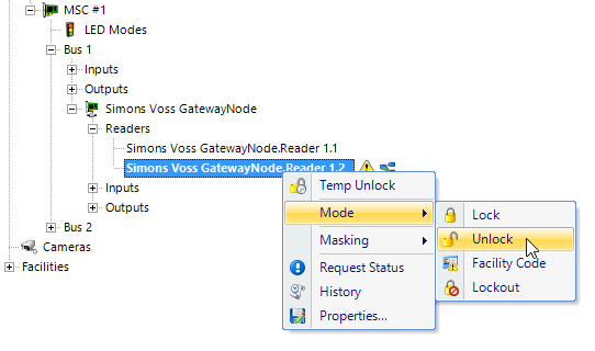
- If you have the reader selected in the hardware tree, you will also see unlock icons in the ribbon bar that you can use.
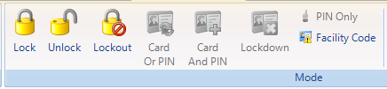
Note: The locks can also be put into 'Lockout' mode (which prevents all cards from gaining access).
11.0 Offline Access List (Whitelist)
The offline access list allows for up to 25 designated cardholders to be able to gain access through the lock (even if the controller is offline to the Doors.NET system). So even if there is a power-outage or controller failure, some cardholders will still be able to gain access at the lock. The Offline Access List can be enabled on a per-lock basis - allowing you to only select the locks that you wish to participate.
11.1 Enable Offline Access List at the Lock
- Select the lock in the hardware tree.
- In the lockset properties on the right, locate the Options.
- Set Enable Offline Access List to Yes.
- Save the Lock Settings.
Note: this will only enable the feature, the next steps explain how the feature is activated.
11.2 Enable Offline Access List in the Cardholder Record
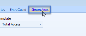
- In Doors.NET go to the Home tab >> Cardholders. When the system is licensed for Simons Voss you will see an additional Simons Voss tab on each cardholder record.
- Open an existing cardholder record or enroll a new cardholder.
- Click on the Simons Voss tab.
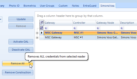
- On the right-side of the screen you will see a list of all locks that have the Offline Access List enabled.
- For a new system you should highlight each lock and then click on the REMOVE ALL button to clear any existing user records (including any construction credentials) - See next section.
- With the lock selected (or multiple locks selected) ensure the cardholder's credential number is selected on the left.
- From the Offline Type drop-down list, select one of the two available options:
- Check with the controller - When a valid card is presented, the lock then does a check that the controller is offline - this will incur approximately a 3-second delay before access is granted.
- Emergency - There is no check if the controller is offline and so access is granted immediately (for example; for emergency services personnel). The credential will be immediately granted access locally at the lock. - Click the UPDATE button and the credential will be updated in the database and will automatically be sent out to the access control network.
Note: The ACTIVATE OAL and DEACTIVATE OAL buttons can be used to immediately enable and disable the offline access list at the selected reader.
12.0 Remove the Construction List From a Lock
The construction list is a list of cardholders that are enrolled into the lock using the Smart Intego software. Typically these cardholders would be enrolled into the lock during the construction phase of a building and it allows you to bring the system fully online in stages. These credentials would typically be removed from the lock once the lock has been added to Doors.NET. The following steps explain how to remove the construction list.
- In Doors.NET, open a cardholder record.
- Click on the Simons Voss tab.
- On the right-side of the screen you will see a list of all locks that have the Offline Access List enabled.
- Select the lock that has the construction list in memory.
- Click the REMOVE CONSTRUCTION button.
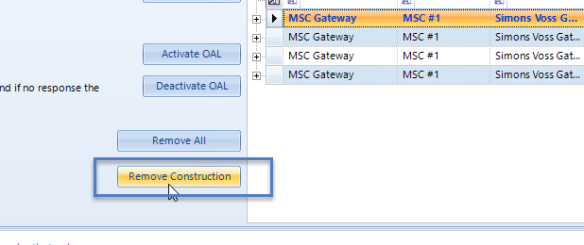
Note: You can also use the REMOVE ALL button to remove all credentials (Whitelist and Construction credential types).
13.0 Low Battery Events
If a lock has a low battery you will see regular low battery events displayed in live events:
- Low battery events - will start to appear 30 days before the battery is completely flat.
- Critical battery events - will start to appear 20 days before the battery is completely flat.
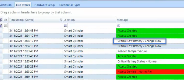
Note: These low batteries events can be used in the Global Linkage menu - so you can configure the system to immediately send you an e-mail message when the battery level is low or critical.
14.0 Office Mode
Doors.NET also gives you the ability to enable office mode on any of the Simons Voss locksets. Office mode allows one or more cardholders to permanently or temporarily unlock a reader with 2 or more valid card presentations within a 3 second time period. This feature is useful if you need to allow non-cardholders access to a room (such as a teacher unlocking a training room for the duration of a lesson). A single card read will grant access as normal but 2 valid card reads within 3 seconds will keep the lock unlocked.
- Go to the hardware tree in Doors.NET (Setup >> Hardware Setup >> All).
- Double-click to expand the controller.
- Select the lockset that you wish to configure.
- Locate Options in the lock settings.
- Set Enable Office Mode to Yes.
- Save the settings and the lock will be immediately updated.
Notes:
- To re-lock the door again, perform another 2-card presentation at the reader and then physically close the door. When re-locking, you will need to hold the credential against the reader for 2-3 seconds.
- This feature requires the use of a door contact as so is therefore only supported on the Smart Handle DM lockset.
15.0 Using a Simons Voss Keypad
The integration gives you the ability to utilize a Simons Voss keypad for PIN or Card + PIN access. The keypad has a 1-to-1 association with an individual lock and is paired using the Doors.NET software.
The following steps explain how to pair a keypad with a lock. Please refer to the Doors.NET help file for instructions about setting up Card + PIN and PIN only access.
- In Doors.NET, go to Setup >> Hardware Setup >> All.
- Expand the hardware tree and select the lock you wish to associate with a keypad.
- In the reader properties on the right, locate the Alternate Reader option, set this to Yes.
- For the Alternate Reader Type, select Simons Voss keypad.
- From the Paired Keypad selection, select the available keypad (which is also communicating to the same gateway node).
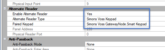
- Save the reader settings.
Note:
- When using a Simons Voss keypad it is not possible to activate Card + PIN with a schedule. Instead the reader mode (i.e Card + PIN mode) is set via a right-click in the Doors.NET software.
- The number of PIN digits for the keypad is setup in the Smart Intego software (the default value is 4).
Related Articles
Simons Voss Gold Standard Certification
GOLD CERTIFIED: Keri Systems has top certification from SimonsVoss Technologies Keri Systems’ reliability, quality, and flexibility have been recognized with Gold Certification from SimonsVoss Technologies, which provides digital locking systems to ...