NXT RIM-WI-PLUS Module Installation Guide
| 1.0 Introduction |
This guide explains how to install and configure the NXT Wiegand-Only Plus Reader Interface Module which is a permanent replacement for the WI (Wiegand-Only) module.
The module connects directly onto one of the communication buses of the NXT or NXT-MSC controller. Once connected, the module configures the controller to recognize Wiegand readers and credentials. The default configuration for the module is for a single-line LED Wiegand reader.
The WI-Plus module supports single line and dual line LED Wiegand readers as well as the NXT-6RK keypad (compatible with NXT credentials).
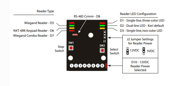
| 2.0 | Wiring and Layout Diagram |
| 3.0 | Wiring Information |
3.1 Reader Wiring Table
Note: For all other Wiegand reader types, please refer to the reader manufacturer's color code.
3.2 Wiegand Reader Wiring Diagram (Single Line LED)
3.2 Wiegand Reader Wiring Diagram (Dual Line LED)
3.2 Reader Shield Grounding
MUST be terminated to one of the following points
- the green ground lug (J6) on the controller (illustrated),
- any corner screw attaching the controller to the enclosure,
- Pin 3 of TB10,
- or the ground lug of the enclosure.

| 4.0 | Specifications |
| 4.1 | Size |
- When mounted on the controller:
| 4.2 | Power/Current Requirements |
- 10 to 14 VDC @ 100 mA (maximum current draw at 12 VDC).
| 4.3 | Operating Conditions |
- 32°F to 150°F (0°C to 60°C) – 0% to 90% Relative Humidity, non-condensing.
| 4.4 | Cable Requirements |
The total RIM to reader cable length must be less than 500 feet.
Note: On long cable runs, cable resistance causes a drop in voltage at the end of the cable run. Ensure the appropriate power and current for your device is available at the device (and at the end of the cable run).
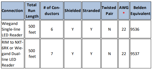
* Note: Heavier gauges than those listed are always acceptable.
| 5.0 | Configuring the NXT RIM-WI Plus |
The RIM-WI Plus can be configured to support any Wiegand-compatible readers or it can support the NXT-6RK keypad. You can also configure the reader for single-line or dual line LED mode. The default settings is for the module to be configured for Wiegand single-line LED. Once in programming mode, first you select which reader type will be used, then you select if it will be single-line or dual line.
- Hold down SW1 and SW2 switches for approximately 4 seconds.
All 7 LEDs will blink three times.
- Release both SW1 and SW2, and the unit is now in configuration mode.
Once in configuration mode, SW1 steps between options - SW2 selects the currently displayed option.
Press SW1 to step through the supported reader types (see the image in section 2.0). Each press of SW1 will step to the next reader type.
When the desired reader type LED is illuminated, press SW2. The reader type is now set.
Once the reader type has been selected you are then ready to configure the RIM’s LED line control mode.
Press SW1 to step through the supported LED line configuration types. Each press of SW1 will step to the next LED line type.
When the desired LED line control mode LED is illuminated, press SW2. The LED line control mode is now set.
Press SW2 twice and the RIM is now configured and the unit reboots to accept the new parameters.
The RIM’s LEDs will be off for about 10 seconds as the unit resets itself. All seven LEDs will flash as the unit is rebooting with the new configuration parameters. When the LEDs stop flashing, the unit is operational.
Note: Do not remove power from the RIM during the reboot process. Loss of power during rebooting will invalidate any configuration changes you have made.
| 6.0 | Verifying RIM Module Configuration |
The corresponding reader type and line control mode LEDs are illuminated during operation. Refer to the drawing in section 2.0 for switch and LED locations, and the table in section 3.0 for switch and LED definitions to confirm your configuration settings.
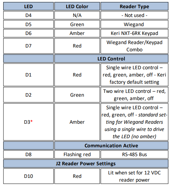
* Table is valid for RIM Firmware v03.01.10 and later. Please upgrade your firmware as necessary.
Related Articles
NXT WI Plus Data Sheet
NXT WI+ Data Sheet (attached)What is the WI Plus Module?
A. The NXT-WI Plus module supersedes the NXT-WI module. As is true with the NXT-WI module, it can only be configured for Wiegand output but you can change the LED mode (single-line or dual line LED mode) using the SW switches on the module. It can be ...NXT-RM3 Module - Installation Guide
1.0 Wiring and Layout Diagrams 1.1 Reader Interface Module (RIM) Diagram Note: This equipment has been tested and found to comply with the limits for a Class A digital device, pursuant to Part 15 of the FCC Rules. These limits are designed to provide ...NXT Port Link Module - Installation Guide
1.0 Introduction The special purpose NXT Port Link is designed for use without an NXT or NXT-MSC controller and its main function is to pass-through 64-bit NXT credential data to a third-party controller. The NXT Port Link module typically connects ...CSA Certificate for NXT RIM Modules
CSA Certification for NXT 4x4 Modules and NXT RIM