NXT Controller Troubleshooting
1.0 Basic Principles of TCP/IP Network Communications
Using the above IP Address example of 192.168.1.1, if the Subnet mask is 255.255.255.0 (Class C), the Network ID would be 192.168.1 while the Host ID would be 1. This Host will be able to communicate to any other device on that network whose IP address is 192.168.1.1 – 254 (255 is reserved for network broadcasts). If the Subnet mask is 255.255.0.0 (Class B), the Network ID would be 192.168, and the Host ID would be 1.1. This Host will be able to communicate to any other device on that network whose IP address is 192.168.0.1 – 192.168.254.254.
Any communication to a device that is on another network (or outside of the Subnet mask) would be passed on to the Gateway, which will route the data to the appropriate Network and Host. If the Gateway does not have a route specified for the destination network, then the communication will fail.
2.0 Controller Responds to an Auto-Config but Does Not Receive the IP Address
- Incorrect IP address range (host PC was outside of the subnet range of the address that was being assigned).
- Firewall may be blocking the communications
For WAN Connections, check the above plus: - Improper, or missing gateway address
- Router not routing traffic
- VPN tunnel may be down
3.0 Controllers are not Detected During an Auto-Config
- Controller has multiple TCP/IP Connections - Try disabling the Wi-Fi network to check this (you get re-enable it again when auto-config is complete).
- Controller is not in a reset state - New controllers will require a factory reset.
- Network cable disconnected - Check the physical network connections from the DoorsNET to the NXT Controller. Look at the Link (D22) and Activity (D33) LEDs on the controller.
- Firewall is blocking communication
- Managed switch is blocking communication ports
- NXT Proxy service is not installed, enabled or in a running state
- Physical hardware problem
For WAN Connections, check the above plus:
- DoorsNXT Proxy Service not installed or running. The DoorsNET Proxy must be installed and running on a computer within the targeted Subnet to allow the Autoconfiguration process to complete.
- Router not routing traffic
- VPN tunnel down
4.0 Controller Update or Controller Status Fails
- Incomplete Autoconfig
- Controller has been reset
- Incompatible controller firmware
- Controller may have been assigned an IP address that is not reachable from the host PC.
For other software based firewalls, please refer to the software documentation on how to add an application to the exception list. For hardware-based firewalls, make sure that Ports TCP/10010, TCP/10020, TCP/10030, TCP/10040, UDP/11067, UDP/11068, UDP/11434, UDP/11435, TCP/3050, and TCP/3060 are allowed to pass through to the computer running DoorsNXT Server, Client, Proxy, and Controllers.
5.0 Router not Routing Traffic
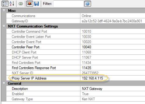
For communication to controllers on different networks or subnets, the Router/Gateway must have a route configured. If a route is configured in the Router, then verify that other devices on the two networks can communicate using the Ping utility. When using Autoconfig to configure controllers on different subnets, make sure the DoorsNET Proxy service is running on a computer installed on the remote subnet and the IP address of that computer is set in the NXT Gateway properties.

Physical Hardware Problem
Check the physical network connections from the DoorsNET to the NXT Controller. Look at the Link (D22) and Activity (D33) LEDs on the controller. The Link LED should be illuminated and the Activity LED will flicker when data is present. If the Link LED is not lit, check the patch cable or replace it with a known good cable. Verify the connection to the switch/hub/router. Check that there is a Link LED at the port.
VPN Tunnel Down
If the communication routes through a VPN, verify that the tunnel is operational. Use Ping or the VPN software to validate connection.
| 7.0 | Tools |
The following tools can be useful when trying to troubleshoot and resolve connection issues. The purpose of these tools is to validate that a connection exists at the lowest network level.
Controller Reset/Default IP
After a system reset, the controller’s IP address reverts to its default IP address of 169.254.1.1. This process should be used if you are unable to complete an autoconfig of a controller and need to validate that the controller is communicating and functioning properly.
In order to communicate to a reset controller, perform the following steps:
Change or add an IP address of the computer to be within the 169.254.x.x subnet using a subnet mask of 255.255.0.0. Example 169.254.0.1.
NOTE: It may not be necessary to change the computer’s IP address, as Windows will often perform an Auto IP and assign an IP address that is within the 169.254.x.x subnet range when it cannot get an address from a DHCP server.
Using a cross over cable to isolate the controller from any other controllers or devices on the network, attempt to connect to the controller using Ping or Telnet.
NOTE: Some network adapters are autosensing and a standard patch cable can be used instead of a cross over cable.
| 8.0 | Ping |
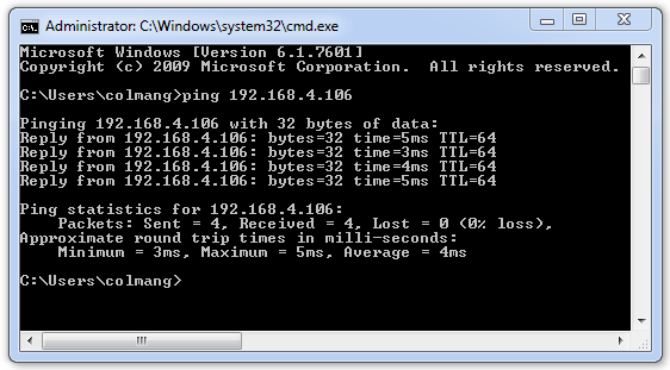
Confirms basic connection route to another networked device. The Ping utility is a command line tool that will send a small packet to the designated device and expect a response from that device. To use Ping, open a command prompt (DOS prompt) by clicking on Start / Run and enter cmd in the Open: field and click on OK. A new window will appear with a command prompt: C:\>. The actual prompt may differ from computer to computer.
To run the Ping command, enter at the command prompt:
C:\>ping <ip address>
Where <ip address> is the IP Address or name of the target device. The ping is successful if a reply is received from the
target device.

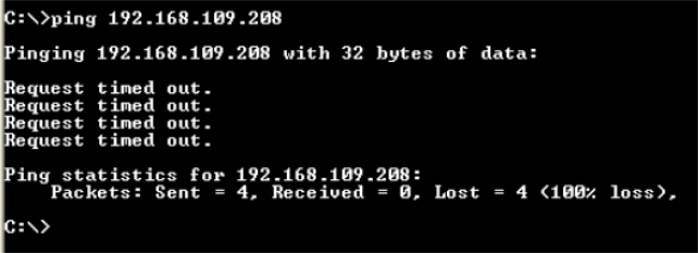
When a ping fails, it will show a Request timed out.

Trace Route
The Trace Route utility displays the route path to a designated network device. If a ping fails, the Trace Route utility can be used to see at which point the packet failed. This tool is especially useful in troubleshooting connections that cross multiple routers. To run the Trace Route utility enter the following command.
C:\>tracert <ip address>
ifconfig
ifconfig displays the IP Address and Subnet settings. At the command line, enter: > ifconfig eth0 (eth0 is the Ethernet interface used in the NXT).
The command will return the following information:
eth0 Link type:6 HWaddr 00:14:34:00:00:01
inet 224.0.0.1 mask 240.0.0.0 broadcast 0.0.0.0
inet 192.168.109.206 mask 255.255.255.0 broadcast 192.168.109.255
UP RUNNING SIMPLEX BROADCAST MULTICAST mtu:1500 metric:1
The HWaddr is the MAC address for the controller and the second inet address and mask are the IP Address and Subnet Mask of the controller.
NOTE: The ifconfig command can be used to change the IP Address and netmask, however changes made using the ifconfig command will not be permanent and should not be done.
netstat
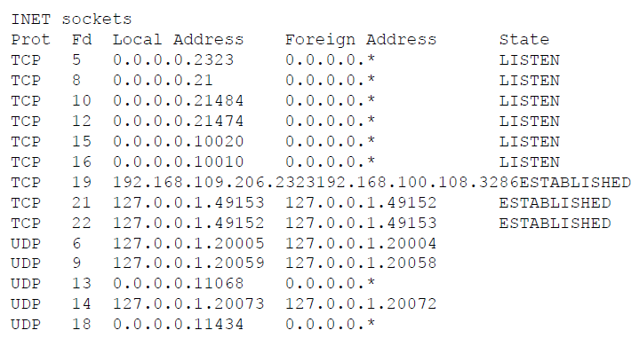
The netstat command displays the network connection ports that are in use and available on the controller. This information is useful to verify that the controller is connected to a DoorNXT server or ready for a connection. At the command prompt enter: netstat –a (the –a switch will provide the status of all connections). The command will return
the following information:

route
Displays Gateway address. At the command prompt, enter the following command to display the Gateway address:
route get
The command will return the following information:
IPv4 default gateway: 192.168.100.1
Related Articles
NXT Controller Firmware Upgrade
When you run the Doors.NET installer you will see an Application Requirements window. This window will inform you if standard NXT controllers need a firmware upgrade and the version they should be upgraded to. There will also be a notification in the ...NXT 4D Controller Data Sheet
NXT 4-Door Controller Data Sheet (attached)NXT 2D Controller Data Sheet
NXT 2-Door Controller Data Sheet (attached)CSA Certification for NXT Controller
CSA Certification for NXT Controllers (attached)NXT 2D/4D Controller Specifications
Size (Enclosure): 13.125” H x 10.625” W x 3.06” D (33.34 cm x 26.99 cm x 7.77 cm) Size (PC Board): 5.6” H x 6.6” W x 2.55” D (14.28 cm x 16.83 cm x 2.55 cm) Weight (In Enclosure): 4.95 Lbs (2.25 Kgs) Input Voltage: + 12 VDC nom. (10 - 14 VDC) Current ...