NXT-MSC - OSDP Reader Support
1.0 Introduction
OSDP (Open Supervised Device Protocol) is an access control communication standard developed by the Security Industry Association (SIA) to improve interoperability among access security products and is being endorsed by all leading access control manufacturers.
Doors.NET v4.9.0 (and later) supports OSDP readers when using the NXT Mercury controllers (NXT-MSC) or the Mercury LP-Series door controllers. OSDP readers, like Keri NXT readers, are fully supervised RS-485 readers and hence are more secure than the most common access control communication protocols. You can also add an OSDP Exit reader by wiring a second reader into the same bus of the controller. The entry reader is addressed as 0 and the Exit reader is addressed as 1, 2 or 3.
Addressing and adding the readers is covered in this document along with an explanation about reader status and supervision.
OSDP Main Features
- OSDP - Two-way AES 128-bit encrypted communications.
- OSDP - The reader (communication status) is supervised - you will know immediately in the software if the reader is compromised and goes offline.
- OSDP reader cable runs can span long distances (up to 4,000 feet).
- You can have more than one reader on the cable run (adding an exit reader).
- Flash firmware makes the readers upgradeable and extends the life cycle of the reader.
- Open standard - Proprietary solutions are often not favored by modern enterprises.
- When readers are OSDP it enables better interoperability among different access control products.
- A trusted standard that is actively being developed by the SIA (Security Industry Association).
2.0 Reader Extension Cable Requirements
The recommended cable type for the reader extension cable is:
- Belden 9841 or equivalent (one twisted pair) for data combined with Belden 8461 or equivalent for the 18x2 power cable. This is physically two separate two conductor cables.
- Belden 9842 or equivalent (two twisted pairs in one jacket).

3.0 OSDP Reader Wiring

4.0 Reader Addressing
IMPORTANT NOTES:
- After adding the OSDP reader in the software, if the reader does not come online you should power-cycle the reader.
- By default, most OSDP readers will be addressed as 0 (so they will be seen by the controller as a standard entry reader). This means if you were to initially connect 2 new readers to the same bus they would both be addressed as reader 0 and will not communicate.
- Some of the older OSDP reader types do not support auto-discovery and so you will need to refer to the manufacturers supporting documentation for details about manually setting the reader address and the BAUD rate locally at the reader (using a third-party utility or reader programming app).
- Once a reader has been configured as an OSDP reader nothing else can be connected to that bus (for example; an NXT 4X4 module) - because OSDP uses a different RS-485 protocol.
- OSDP readers cannot have more than one reader on a bus addressed as 0. Once an OSDP reader has been addressed as 0 you should disconnect the reader from the bus and then connect the next reader you wish to configure. It is not enough to just disable the polling to the first reader.
5.0 Adding a Single OSDP Reader
This assumes you already have an NXT-MSC controller added and online in Doors.NET and it also assumes both readers support auto-discovery. Also ensure Advanced View is enabled for the reader properties.
- From within Doors.NET, go to Setup >> Hardware Setup >> All to display the hardware tree.
- Expand the controller and select the reader that is an OSDP reader. The reader properties will be displayed on the right.
- From the Manufacturer Model drop-down menu, select the model as 'Generic Wiegand' (near the top of the list).
- Ensured that Advanced View is enabled for the reader properties.
- Scroll down the properties until you locate LED/Buzzer. Set this to 'OSDP reader'.
- Scroll back to the top of the reader settings and the model will now be displaying as 'Generic OSDP Reader'.
- Change this to 'Generic OSDP Reader with Keypad' if there is a keypad present. Save the reader settings.
Note: As you will see, in the previous image, the default address number is 0 - so if you only have a single reader connected, the controller will start communicating with the reader as soon as the reader settings have been saved.
6.0 Adding an OSDP Exit Reader
When adding a second reader to the bus you should setup the readers individually as per the following instructions - (because communication will not be possible when both readers have the same default address 0). The following steps require you to be logged into Doors.NET as a system administrator. If the system will be using multiple entry and exit readers you could configure (and label) all the readers as either exit readers or entry readers prior to going to site - if you have an NXT-MSC controller and an installation of Doors.NET V4.9.0 (or later) to use.
6.1 Connect and Setup the Exit Reader
- Physically disconnect the Entry reader.
- Physically connect the Exit reader.
- Within a few seconds the reader will come online as the Entry reader.
- Select the bus.
- Click the Add NXT icon.
- You will see a notification that the Exit reader's OSDP address will be changed.
- The OSDP Exit reader will appear on the hardware tree beneath the ENTRY reader.
- In the upper-left of the admin client, click on the Design Mode icon - Design Mode will be enabled.
- Right click on the reader you added and select OSDP >> Auto Discovery.
- Within a few seconds the reader will show online as the Exit reader.
- Click the Design Mode icon again to disable Design Mode.
- Physically connect both the Entry reader and the Exit reader into the same bus.
- Within a few seconds both OSDP readers will show as online.
7.0 Auto-Discovery Change Address
The newer OSDP readers support 'auto-discovery' this will allow you to change the reader's address from the Doors.NET soft ware (again, this requires you to be logged into Doors.NET as a system administrator and you will need to momentarily enable Design Mode). Refer to the reader documentation for details about changing the reader's address if the reader does not support Auto-Discovery.
- Enable Design Mode (via the Design Mode icon):
- Select the reader in the hardware tree.
- In the reader properties, change the reader address number.
- Save the reader settings.
- Right-click the reader in the hardware tree and select OSDP >> Auto-Discovery.
- The reader will momentarily go offline. Once it is back online it will be configured with its new address.
8.0 OSDP Reader Supervision
Because the OSDP readers are fully supervised, if the reader is disconnected there will be an event displayed in live events.
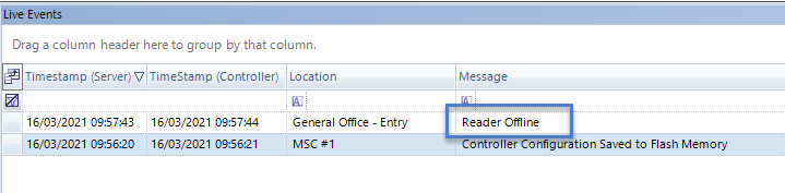
You can configure this event type to generate a sound alert at the PC or you could configure an e-mail or SMS message to be immediately sent out to a designated recipient.
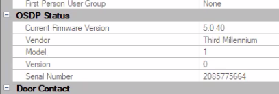
9.0 OSDP Status Information
- The Doors.NET software will detect the reader vendor, the model, the version number and the reader serial number (which you can view by selecting the reader in the hardware tree). The reader properties display on the right.
- Scroll down the reader properties and locate OSDP Status.
- The reader vendor and model details will be displayed.
10.0 OSDP Reader Firmware Upgrading
To be implemented in a future Doors.NET release.
Related Articles
NXT-MSC 2D Data Sheet
NXT-MSC (Mercury-Powered) 2-Door Controller Data Sheet (attached)NXT-MSC 4D Data Sheet
NXT-MSC (Mercury-Powered) 4-Door Controller Data Sheet (attached)NXT-MSC Hardware Cable Requirements
The attached document provides you with the required cable types to use when installing NXT-MSC 2 door or 4 door controllers.NXT-MSC v1.293 Firmware Release Notes
1.0 NXT-MSC Controller Firmware Release MSC controller firmware v1.293 addresses the following issue: • Corrected an issue where the strike time for 4x4 and GIOX units under elevator control stayed active longer than the strike time set for the ...NXT-MSC Controller - Advanced and Extended Features
1. 0 Introduction The NXT-MSC (Mercury-Powered) controller is programmed with the firmware of a Mercury EP1502 controller. It has all the standard and advanced functionality of an EP1502, such as: temporary cards (by use count, number of days or ...