PXL-500 Quick Start Guide
1.0 Introduction
For information regarding the use of the PXL-510 controller in connection with the NetworX1 NX-8E Alarm Panel, please refer to the NetworX NX-8E Alarm Panel Application Note (P/N 01919-001). For information regarding a Time and Attendance Terminal, please refer to the Time and Attendance Terminal Application Note (P/N 01943-001).
Note: It is the responsibility of the installation organization to have only technically qualified personnel performing the installation.
Note: All references to the PXL-500 may be applied to the Time and Attendance Terminal.
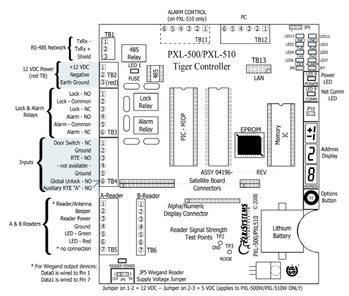
2.0 PXL-500 Controller Wiring Diagram
3.0 Specifications
3.1 Unit Dimensions
• PXL-500/PXL-510 controller PCB
- 6.75 inches high by 6.00 inches wide by 1.75 inches deep, including wiring connectors
- (17.15 cm by 15.25 cm by 4.45 cm)
• PXL-500/PXL-510 controller PCB with an LCD-1 Alpha/Numeric Display
- 7.70 inches high by 6.00 inches wide by 1.75 inches deep, including wiring connectors
- (19.60 cm by 15.25 cm by 4.45 cm)
• PXL-500/PXL-510 controller PCB with an SB-593 Satellite Board (with or without an LCD-1 Alpha/Numeric
Display)
- 7.25 inches high by 6.00 inches wide by 1.75 inches deep, including wiring connectors
- (18.45 cm by 15.25 cm by 4.45 cm)
• Enclosure
- 13 inches high by 9 inches wide by 4 inches deep
- (33.02 cm by 22.86 cm by 10.16 cm)
3.2 Operating Temperature/Humidity Range
• 0°F to 140°F (-18°C to 60°C)
• 0% to 90% Relative Humidity, non-condensing
3.3 Controller Power Requirements
• 12 VDC @ 1 A
3.4 Current Draw
• maximum current draw 270 mA for a controller plus reader current draw (refer to Table 1 for Reader current draw)
• 120 mA max for a PXL-500/PXL-510 Controller
• 150 mA max for an SB-593 Satellite Board
Table 1: Reader Current Draw
Note: If an electronic locking device (such as a magnetic lock, a door strike, or similar device) is to be driven by the same power supply as the PXL-500/PXL-510 controller, please ensure the power supply provides enough current to drive every device connected to that supply plus an adequate safety margin. AC power is not recommended.
3.5 Controller Memory Retention
• 5 year lithium battery back up to support controller RAM and real-time clock
3.6 Output Relay Contact Rating
• 1 Amp @ 24 VDC
3.7 Input Device Configuration - 3 Inputs
• Door Sense normally closed
• Request to Exit normally open
• Global Unlock normally open,
or Auxiliary RTE A-Door normally open
4.0 Cable Requirements
4.1 RS-232 Serial Cable
• four conductor, shielded, stranded, AWG 24 wire (Belden 9534 or a larger gauge)
• 50 feet maximum length (per RS-232 industry specification - greater lengths are not recommended)
4.2 RS-485 Network Cable
• two conductor, shielded, twisted pair, stranded, AWG 24 wire (Belden 9501 or a larger gauge)
• 16,000 feet total network length
• refer to the Network Wiring Application Note (P/N 01824-002) for specific network wiring information
Note: When wiring the RS-485 terminal block connector, be sure to use the smallest connector provided. TB1 is smaller than the other terminal blocks and will only accept the smallest terminal block connector provided.
4.3 Input Power
• two conductor, stranded, AWG 18 wire (Belden 8461 or a larger gauge)
• 200 foot maximum length for systems using an SB-293 with two readers
Note: On long power cable runs, the cable resistance causes a drop in voltage at the end of the cable run. Be sure your power supply does provide 12 VDC at the end of the cable run.
4.4 Earth-Ground Connection
• Single conductor, AWG 18 wire (or a larger gauge)
4.5 Keri Proximity Readers
• six conductor, shielded, stranded, AWG 24 wire (Belden 9536 or a larger gauge)
• four conductor, shielded, stranded, AWG 24 wire (Belden 9534 or a larger gauge) for the MS-4000 only (there is no
beeper or LED in the MS-4000)
• see Table 2 for maximum cable lengths
Table 2: Maximum Cable Lengths by Wire Gauge for Proximity Readers
| Cable Length by Wire Gauge | |||
| Reader Type | 100 feet | 250 feet | 500 feet |
| MS-3000 | AWG 24 | AWG 24 | AWG 24 |
| MS-4000 | AWG 24 | AWG 24 | AWG 24 |
| MS-5000 | AWG 24 | AWG 24 | AWG 24 |
| MS-7000 | AWG 24 | AWG 24 | AWG 20 |
1. Ground wire is green with or without yellow tracer.
4.6 Wiegand Compatible Readers
• four to seven conductor, shielded, stranded, wire – depending upon the Wiegand reader’s requirements
• a minimum gauge of AWG 24 is required for data transfer with a 500-foot maximum run length per Wiegand specification.
4.7 Input and Output Connections
• two conductor, stranded, AWG 22 (or a larger gauge)
Note: The Lock Output relay may require a heavier gauge of wire depending upon the current demands of the lock and the length of the lock wiring run.
Note: If plenum cable is required, please reference the Belden plenum equivalent to the cables listed above.
5.0 PXL-500 Installation Recommendations
DO
• plan ahead to meet power and any telephone requirements2
for your system (1 phone line for the modem connected to
the host computer and one for each Primary PXL-500/PXL-510 in each network)
• mount controllers in environmentally suitable areas - they require protection from weather and from temperature/
humidity extremes
• if not using a KPS power supply, mount the controller at least 3 feet away from the controller's power supply to
prevent EMI radiated from the power supply from affecting the controller
• use the enclosure as a mounting template to mark drilling holes for permanent mounting
• consider mounting requirements - central versus distributed
- central mounting places all controllers in one location, running lengths of cables out to each door to support
readers, inputs and outputs
- distributed mounting places each controller near the door it supports running short lengths of cable out to each
door, but running a long network communication cable
• note the locations of the knockouts in the enclosures and remove the appropriate knockout for the easiest cable
routing into the controller
• route all controllers in a network in a single, continuous daisy-chain
• route cables in accessible areas for ease of maintenance
• connect all controllers to a quality earth ground3
• add transient suppression across electric devices attached to a controller output
• use an isolation relay (P/N IRP-1, or equivalent) if attaching to an elevator, a parking gate, a turnstile, or any
application using a large electric motor
• verify the controller's supply voltage is 12 VDC – long power line runs cause a drop in voltage at the end of the run
• verify proper operation of the host computer's COM port
• for a single door application, install the reader to the TB-5, "A" reader connection
• attach the reader to be used for card enrollment to the Primary controller (this reader can be used for access control as
well as enrollment, but during the enrollment process the door associated with the enrollment reader will not allow
access until the enrollment process is complete)
• If using Wiegand readers, check the voltage requirements of the reader (+5 VDC or +12 VDC at the device). A PXL-500W has a reader power voltage jumper in the lower left corner (marked JP5) - This configures to the reader port to output either 5 or 12VDC.
DO NOT
- make modem phone line connections through PBX telephone switching systems - most modems are not compatible with PBX systems leading to disconnection problems with the modem
- locate the PXL-500/PXL-510 controller near EMI sources - EMI sources can affect the performance of the controller
- use switching power supplies - they are EMI sources
route network and reader cables beside power cables - transients on the power cables may be picked-up by network and reader cables
stretch or over-tension cables
- route over sharp objects
let the wires get tangled
- route controllers in a network in a loop configuration
connect earth-ground to the network cable shield - the PXL-500/PXL-510 automatically connects earth ground to the shield at one point on the network to prevent ground loops
- use gender changer plugs when making RS-232 serial communication connections (unless you know it is a “straight-through” plug) - gender changers may have internal wiring changes that can disrupt communications
6.0 Wiring Instructions
Refer to the image on page 1 for all controller wiring connections.
6.1 Terminal Blocks

Figure 2: Connecting Wires and Removing Terminal Blocks
Note: Screws on terminal blocks must be tightened securely.
6.2 Connecting the Earth-Ground and the 12VDC Input Power
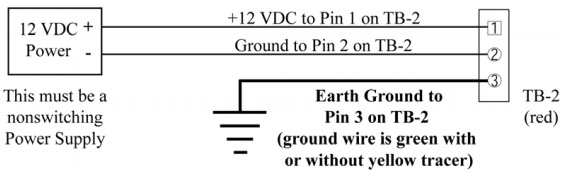
Figure 3: Earth Ground and 12 VDC Power Connections
Note: TB2 is colored red to make it easier to tell it apart from the network connector
6.3 Connecting a Keri Systems Proximity Reader to a PXL-500P
- The "A" reader is wired to TB5.
- The "B" reader is wired to TB6.
6.4 Connecting a Wiegand Compatible Reader to a PXL-500W
The PXL-500W controller can be configured to accept input from single-line LED, dual-line LED, and Essex keypad Wiegand input devices (through the Doors.NET™ software).
Note: The Wiegand Reader must transfer data according to the Security Industry Association's Wiegand Reader Interface Standard (document number AC-01D-96). Keri Systems, Inc. cannot guarantee the performance or reliability of Wiegand Readers that do not meet these data transfer guidelines.
Note: All Keri Systems proximity readers use 12 VDC power while some Wiegand compatible readers use 5 VDC power. Check your reader's power requirements and verify jumper JP5 is set correctly per the Verify the Wiegand Reader Supply Voltage requirements.
Note: The wire colors called out in diagram below are industry standard wire colors. However, some manufacturers may not follow these industry standard designations. Before installation, please refer to the Wiegand device’s manual to see if the device’s wire colors follow the industry standard. If not, then match the wire’s purpose to the call outs in the diagram below.
6.5 Connecting a Door Status Input
Each PXL-500 is shipped with an installation kit including all necessary terminal blocks and transorbs. One of these terminal blocks has a jumper across pins 1 and 2. This terminal block is designated for use on TB-4. If a door switch is not used on the controller, this jumper prevents a continuous door open status alarm from being received by the controller. If a door switch is used, simply remove this jumper and install the door switch leads.
Open door to open circuit and activate door switch input
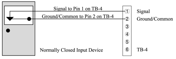
Figure 7: Door Status Input Connections
Note: A Door Switch must be installed on any door to which anti-passback is being applied for proper tracking of the anti-passback feature in the Doors program.
6.6 Connecting a Request to Exit (RTE) Input
Press button to close circuit and Activate RTE A-Door Input
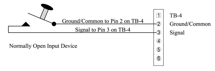
Figure 8: Request to Exit Input Connections
6.7 Connecting a General Purpose Input
The general-purpose input is used in conjunction with the programmable input/output feature of the Doors access control software. There are three possible uses for the general-purpose input.
• the Primary controller may be figured for either Global Unlock (see figure 9) or Auxiliary A-door RTE (see figure 10)
• the Secondary unit may be figured for Auxiliary A-door RTE (see Figure 10)
Make the following connections for a Global Unlock input.
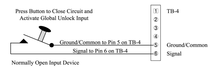
Figure 9: Global Unlock Input Connections
Make the following connections for an Auxiliary A-door RTE input.
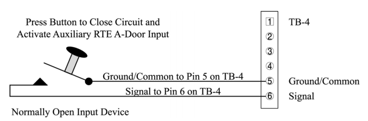
Figure 10: Auxiliary A-Door RTE Input Connections
6.8 Connecting an Alarm Output Relay
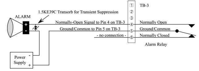
Figure 11: Alarm Output Relay Connections
6.9 Connecting a Fail-Safe Lock Output Relay
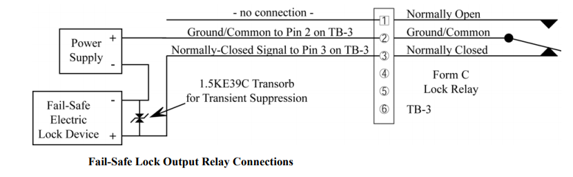
Figure 12: Fail-Safe Lock Output Relay Connections
6.10 Connecting a Fail-Secure Lock Output Relay
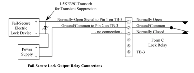
Figure 13: Fail-Secure Lock Output Relay Connections
6.11 RS-485 Network Connection
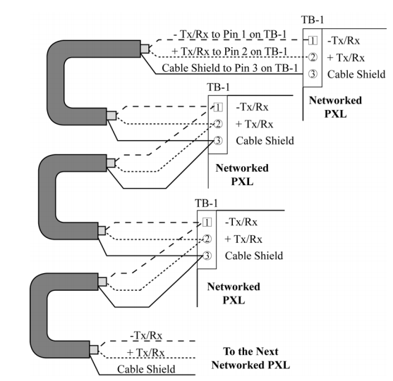
Figure 14: RS-485 Network Connections
7.0 Communication between the Access Control Network and Host Computer
Communication between the access control network and the host computer may be made via one of three ways.
• A direct connect cable between Primary controller and host computer via the RS-232 serial port.
• Use of a LAN-520 module to provide LAN/WAN Ethernet connectivity between Doors.NET and one or more PXL networks. The LAN-520 uses TB13 port to connect to the controller. For information about setting up a PXL-500 with a LAN-520 click here.
• When using a LAN-520 for ethernet communication, the jumpers across JP6 and JP7 must be removed.
8.0 Powering the PXL-500 Controller for the First Time
Note: Verify the earth ground1 has been connected at pin 3 of TB-2 before turning the power on for the first time.
Note: Do not connect the 12 VDC power supply’s terminal block output to the TB-2 connector on the PXL-500/PXL-510 controller until you have completed all the steps in section 5.1.
8.1 Verify the 12VDC Power Input Supply
To verify the 12 VDC supply voltage:
1. Set the DVM to a DC volt scale capable of reading 12 VDC.
2. Turn the power supply ON.
3. Place the Red DVM lead on the power supply’s terminal block output - Pin 1.
4. Place the Black DVM lead on the power supply’s terminal block output - Pin 2.
5. Check the DVM reading. It should read between +12 VDC to +14 VDC.
6. If the DVM does not read between +12 VDC to +14 VDC, verify the power supply is of the correct voltage, verify the
cable length does not exceed 200 feet, and verify the cable gauge is AWG 18. This problem must be corrected before
power can be supplied to the controller.
7. Turn the power supply OFF.
8. Connect the power supply’s terminal block output to the TB-2 connector on the PXL-500/PXL-510 controller.
9. The controller is now ready to be powered ON.
Note: On long power cable runs, keep in mind the resistance in the cable itself causes a drop in voltage at the end of the run. The power supply must be able to account for this voltage drop.
8.2 Verify the Wiegand Reader Supply Voltage
All Keri Systems proximity readers can use from 5 to 12 VDC power while some Wiegand compatible readers use only 5 VDC. For Wiegand configured PXL-500/PXL-510 controllers, there is a warning LED on the mother board to indicate if the controller is applying 12 VDC to the Wiegand compatible reader. If your Wiegand compatible reader does operate on 5 VDC no changes need to be made; the default position for the jumper is set to 5 VDC power. If your Wiegand compatible reader requires 12 VDC, turn the controller power off and move the jumper on JP5 (at the lower left-hand corner of the controller) from pins 2-3 to pins 1-2. When power is restored, the warning LED will turn on indicating 12VDC is being supplied to the Wiegand compatible reader.
Related Articles
SB-593 Hardware Installation Guide
1.0 Important Note: Keri Public Statement on the Amazon Key Keri Systems, Inc. has updated its policy regarding the integration of Amazon devices with Keri Systems controllers. We are pleased to inform you that Amazon has now provided official ...PXL-500 Hardware Installation Guide
PXL Controller Installation Guide 1.0 Introduction This document contains installation guidelines and wiring diagrams for the installation of the PXL-500 Controller. Notes: A Serial connection is only supported when using the Doors.NET software. If ...PXL-500 Troubleshooting Guide
Following is a list of possible scenarios you may encounter when setting up or using the PXL-500 controllers. You will then see a possible solution or a list of possible solutions listed in order of the most likely cause: 1.0 Controller Communication ...PXL-500 Controller Data Sheet
PXL-500 Controller Data Sheet (attached)PXL-500G Vehicle Access Controller
PXL-500G Vehicle Access Data Sheet (Attached).