LAN-520 and NC-485 Network Converter Setup Guide
1.0 Introduction
This document discusses how to setup, configure, and use the LAN-520X and NC-485X Network Converter to provide LAN/WAN Ethernet connectivity between a PXL-500 primary controller and one or more PXL secondary controllers.
The following topics are covered:
• Overview
• Controller Setup
• Configure the Primary LAN-520X Module
• Configure the Secondary LAN-520X Module
• Using Multiple PXL Networks on the Same LAN Subnet
• Basic lan-520 and Ethernet Troubleshooting
Note:
- The NC-485X is an updated version of Keri’s NC-485 device. If you are using the new NC485X with a LAN-520, you must use the updated LAN-520X module. The original NC-485 Network Converter is NOT compatible with the new LAN-520X.
- These instructions also apply to the LAN-520AES module (which is also compatible with the NC-485X).
2.0 Overview
The LAN-520X, when used in conjunction with a NC-485X, provides you with the ability to use existing LAN/WAN for RS-485 communication between a Primary PXL and multiple Secondary PXLs.
Since LAN/WAN networks can be global, using the LAN-520X with a NC-485X provides the ability to have Secondary PXLs located throughout the world managed from one central location.
The LAN-520X supports two communication channels. Channel 1 is used for RS-232 communication and Channel 2 is used for RS-485 communication. The RS-232 communication is identical to that of a LAN-505. The LAN-520X replaces the LAN-505 for serial over Ethernet communication. In order to provide RS-485 communication over Ethernet, the LAN-520X must be connected to the NC-485X Network Converter.
The drawing below shows a conceptual PXL network. Each PXL network segment contains one LAN-520X connected to a NC-485X. The network segment containing the Primary controller (controller #1), must have the LAN-520X/NC-485X connected. Only one LAN-520X/NC-485X combo can be installed on a network segment. A maximum of 48 network segments can be connected to a PXL Primary. It is also possible to connect a PXL network outside of the Local LAN by utilizing a VPN or WAN.
As you can see, some of the controllers are on a different physical subnet, but by using the LAN-520X/NC-485X combo the controllers can be addressed as though they were on the same physical network.
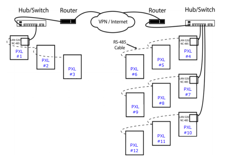
Figure 1: Single Site with Multiple Network Segments
3.0 Controller Setup
(These instructions apply to the Primary and Secondary PXL Controllers).
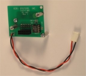
3.1 Connect the NC-485X to the PXL-500
- J102 on the NC-485X connects into the TB-13 LAN connector on the PXL controller.
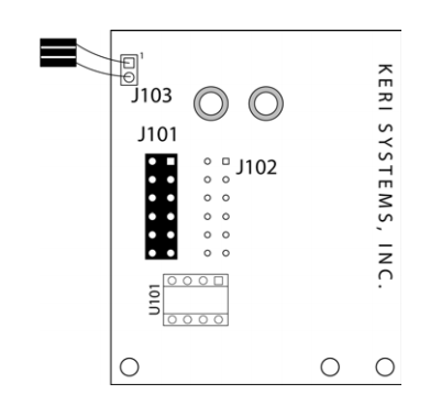
Figure 2: The NC-485X Network Converter The 2-conductor lead (J103) connects to the JP-9 connector located at the top right corner of the PXL-500.
Pin 1 of J103 on the NC-485X connects to Pin 1 of JP-9 on the PXL-500 (see Figure 3).
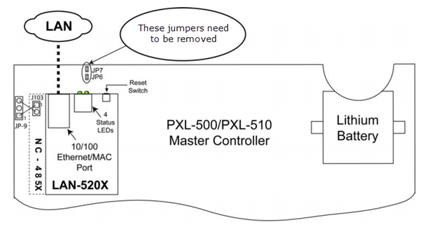
Figure 3: Installation of the LAN-520X with NC-485 Network Converter- On the controller, you should remove the jumpers from the JP6 and JP7 pins, this configures the controller to use the LAN-520 module, as opposed to a Serial connection.
4.0 Configure the Primary LAN-520 Module
The LAN-520X can be configured in one of two modes: Primary mode or Secondary mode. The LAN-520X connected to PXL-500 controller #1 should be configured as Primary Mode and the LAN-520X connected to a secondary controller (addressed something other than controller #1) should be configured as Secondary Mode.
This section assumes that the LAN-520 modules are already configured with the required IP address. If not refer to the LAN-520 Quick Start Guide (P/N 01504-001) for further instructions.
Note: You should make a note of the IP address that is configured on the LAN-520 connected to controller #1 - this IP addressed will need to be entered when configuring any of the Secondary LAN-520 modules (See section 5.2).
4.1 Connect to the LAN-520X via Telnet
There are a few critical parameters to set via Telnet, all other parameters should be left at their default values. There are two ways to connect using Telnet, through the Lantronix DeviceInstaller, or by opening a command prompt window.
- From the DeviceInstaller screen, locate and double-click on the IP address of the LAN-520X. Select the Telnet tab and then click on the CONNECT button.
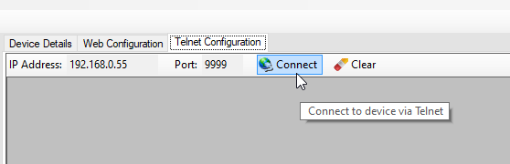
Figure 4: Lantronix Device Installer Telnet CONNECT button - As soon as the Telnet sign-on screen appears, press <Enter> to go into the LAN-520X Setup mode. There is a two to three second window in which you must press <Enter> before the Telnet session automatically closes. If the Telnet session closes before you enter Setup mode (if nothing happens when you press <Enter>), simply click the box again to establish the connection.
- Once Telnet connects with the LAN-520X all current configuration information is displayed and the cursor is placed at the “Your choice” field.
4.2 LAN-520 Primary Channel 1 Settings
The default Channel 1 configuration settings for the LAN-520X are sufficient for the LAN520X Primary. To set the default values for channel 1, enter 7 at the 'Your Choice' prompt and click <ENTER>.
4.3 LAN-520 Primary Channel 2 Settings
If a configuration value needs to be changed, type the new value and the original value is overwritten. Every time <Enter> is pressed, the displayed configuration value is accepted and the next parameter is displayed.
- At the 'Your Choice' prompt, enter 2 <ENTER> to enter the channel 2 configuration values.
- Press <Enter> until the I/F Mode parameter is displayed. This value must be 4F for proper communication between LAN-520Xs over RS-485. If this value is not 4F, type 4F to overwrite the original value.
Press <Enter> until the Port parameter is displayed. This value must be 10002 for proper communication between Doors.NET and the LAN-520X. If this value is not 10002, type 10002 to overwrite the original value.
Note: This value should not be changed unless multiple PXL networks are on the same LAN Subnet (see “Using Multiple PXL Networks on the Same LAN Subnet” - section 6.0) or instructed to do so by either Keri Systems or Lantronix Technical Support Staff.- Press <Enter> until the Connect Mode parameter is displayed. The default for this value is 0C. If all LAN-520X units are within the local subnet, leave the default as is. If one or more LAN520Xs are located outside the local subnet, this value must be overwritten to 2C for Primary controllers to enable use of Hostlist.
Press <Enter> until the Remote IP Address parameter is displayed. Setting the remote IP address will designate this unit as a Secondary. Leave it at the default (0.0.0.0).
- Press <Enter> until the Hostlist parameter is displayed. The Hostlist parameter is only displayed if the Connect Mode has been set to 2C. This option may be configured for up to 12 remote Secondary IP addresses on different LAN subnets. Setting this parameter will designate this unit as a master.
Press Y <Enter> to add or change the IP addresses and Port numbers of the Secondary units. Enter the IP address and Port number for each Secondary unit. The Port number should be set to 10002.
- Once all the IP addresses and Port numbers have been entered, press N when the “Change Hostlist? (N)” option is displayed
- Press <ENTER> through the remaining channel 2 settings until the Change Setup menu appears.
- Review the channel 2 settings, ensure they are displayed as highlighted in the following image.
Figure 5: Correct Channel 2 Configuration Parameters - Primary Unit - Press 9 <Enter> to save the assigned Channel 2 configuration parameters. A “Connection to host lost” message appears. Click the box to clear the connection lost message, then close the Telnet and CMD prompt windows. The Channel 2 configuration parameters are now entered into the LAN-520X’s configuration table.
5.0 Configure a Secondary LAN-520 Module
There are a few critical parameters to set via Telnet, all other parameters should be left at their default values. There are two ways to connect via Telnet, through the Lantronix DeviceInstaller, or by opening a command prompt window. This example uses Lantronix Device Installer utility.
5.1 LAN-520 Secondary Channel 1 Settings
Again, the default Channel 1 configuration settings for the LAN-520X are sufficient for the LAN520X Secondary. To set the default values for channel 1, enter 7 at the 'Your Choice' prompt and click <ENTER>.
5.2 LAN-520 Secondary Channel 2 Settings
If a configuration value needs to be changed, type the new value and the original value is overwritten. Every time <Enter> is pressed, the displayed configuration value is accepted and the next parameter is displayed.
- From the DeviceInstaller screen, locate and double-click on the IP address of the LAN-520X. Select the Telnet tab and then click on the CONNECT button.
As soon as the Telnet sign-on screen appears, press <Enter> to go into the LAN-520X Setup mode. There is a two to three second window in which you must press <Enter> before the Telnet session automatically closes. If the Telnet session closes before you enter Setup mode (if nothing happens when you press <Enter>), simply click the box again to establish the connection.
Once Telnet connects with the LAN-520X all current configuration information is displayed and the cursor is placed at the “Your choice” field.
Press 2 <Enter> to enter the Channel 2 Configuration values. The second configuration parameter is displayed.
Press <Enter> until the I/F Mode parameter is displayed. This value must be 4F for proper communication between LAN-520Xs over RS-485. If this value is not 4F, type 4F to overwrite the original value.
- Press <Enter> until the Connect Mode parameter is displayed. This value must be 0C for Secondary units. If this value is not set correctly, overwrite it with the correct value stated above.
Press <Enter> until the Remote IP Address parameter is displayed. This value must be set to the IP address of the LAN-520X Primary. Setting the remote IP address will designate this unit as a Secondary. The Secondary will only respond to messages from the designated Primary IP address.
- Press <Enter> until the Remote Port parameter is displayed. This value must be 10002 for proper communication between Doors.NET and the LAN-520X. If this value is not 10002, type 10002 to overwrite the original value.
Note: The Port number should not be changed from 10002 unless multiple PXL networks are on the same LAN Subnet (see “Using Multiple PXL Networks on the Same LAN Subnet” - section 6.0) or instructed to do so by either Keri Systems or Lantronix Technical Support Staff. Press <Enter> until the Change Setup menu appears.
Press 9 <Enter> to save the assigned Channel 2 configuration parameters. A “Parameters stored...” message appears and the connection is closed. You may now close the Telnet window. The Channel 2 configuration parameters are now entered into the LAN-520X’s configuration table.
Figure 6: LAN-520X Secondary Channel 2 Settings.
6.0 Using Multiple PXL Networks on the Same LAN Subnet
If two or more PXL Networks using RS-485 over Ethernet exist on the same local subnet, it is recommended that each LAN-520X Primary have a different Channel 2 port number.
For each PXL Network, change the Channel 2 Port setting on the LAN-520X Primary and Secondary controllers to a unique number. It is recommended that the port number be incremented by one digit for each network. The first network’s LAN-520X Primary Channel 2 Port is set to 10002, next Port is 10003, etc. Next, change each of the Channel 2 Remote IP Address for the LAN-520X Secondary controllers to correspond to their LAN-520X Primary’s Port number.
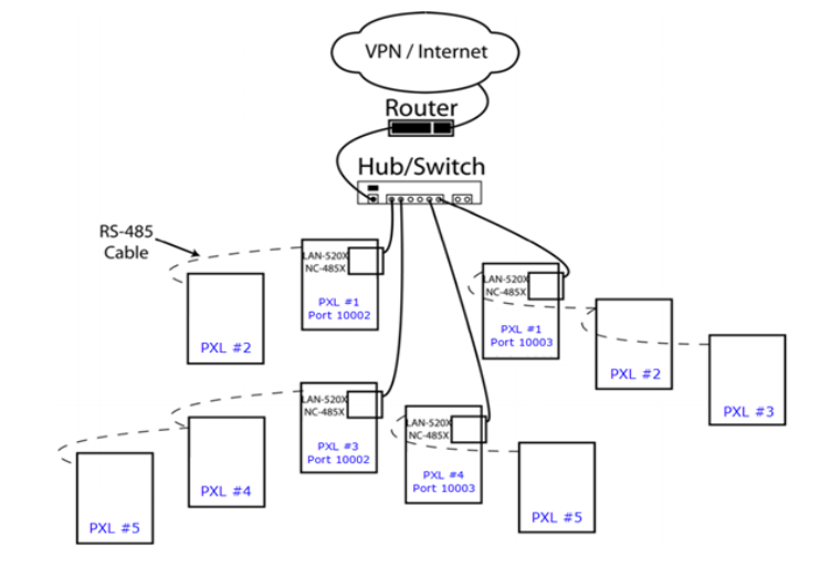
Figure 7: Multiple PXL Networks on the Same LAN Subnet
7.0 LAN-520X/NC-485X Troubleshooting Guide
This section provides some basic troubleshooting information should you have trouble connecting to or using a LAN-520X.
Note: This section assumes you have a working knowledge of computer networks. For the troubleshooting process, you should consult with the system or network administrator.
7.1 PXL Primary Showing as Offline in Doors.NET
- Check the LAN-520 IP address and port number is correct in the Doors.NET software. The IP address should match the address which has been programmed in the LAN-520.
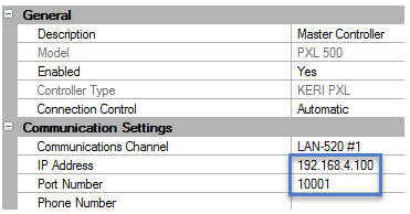
By default, the Server's Ethernet Port Number is set to 10021 and should not be changed unless it conflicts with another device on the host workstation.
- By default, the Remote Site Port Number is set to 10001 (both in the device and in the Doors.NET software). You can check this by making a Telnet connection to the device and check this value in the Channel 1 settings. This value should be at 10001 unless you have been instructed to change it by an IT or Network Administrator.
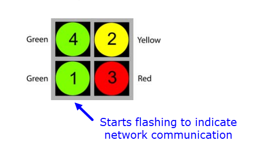
- When the PXL gateway attempts to connect with the LAN-520 on controller #1, the lower green network status LED should start flashing.
- Verify that the JP6 and JP7 jumpers on the Primary PXL controller have been removed (this configures the controller for Ethernet communications).
Verify that the Primary PXL controller is addressed as number 1.
- Ensure the PC is on the same IP range as the LAN-520. The best way to check this is to run Lantronix Device Installer and verify in Lantronix Device Installer that the module shows as online.
7.2 The LAN-520 Has a Flashing Red LED
- The LAN-520 may have malfunctioned
- The LAN-520 has been assigned an IP address which already exists on the network.
- The LAN-520 may not be properly connected to the TB13 Ethernet port.
7.3 The LAN-520 Only has the Top Green LED Illuminated
- Verify that the Ethernet cable is not disconnected at the LAN-520 or the network hub/switch.
- Verify that the network hub/switch has not developed a fault.
- If using a cross-over cable check that the Ethernet cable is plugged into the PC
7.4 Cannot Ping the IP Address of the LAN-520
- There is no power to the LAN-520 unit.
- The IP address may not be programmed properly.
- Another device on the network has that same IP address (you should be seeing a flashing red LED on the unit if this is the case).
- The workstation has not been granted access to that segment of the network.
Related Articles
LAN-520 - Quick Start Guide
1.0 Introduction The following are basic setup instructions for the LAN-520 module. Some settings may not apply to every application. Note: The LAN-520 AESP is an updated version of Keri’s LAN-520X device. If you are using the new NC-485X Network ...LAN-520-AESP - Quick Start Guide
1.0 Introduction The following are basic setup instructions for the LAN-520-AESP module. Some settings may not apply to every application. Note: The LAN-520 AESP is an updated version of Keri’s LAN-520X device. If you are using the new NC-485X ...LAN-520 AESP - Full Installation Guide
1.0 Introduction The following are basic setup steps for the LAN-520 AESP. Some settings may not apply to every application. The following setup instructions explain how to use Lantronix Device Installer to find the DHCP assigned IP address and then ...LAN-520 - Enhanced Security Settings
1.0 Introduction If the LAN-520 channel 1 port # has been changed to 1234 then this is highly indicative that the device has been hacked. The default value for the port number is 10001. This is the number that identifies the channel for remote ...LAN-520 Data Sheet
LAN-520 Ethernet Connectivity Data Sheet (attached)