OSDP Reader Setup in Doors.NET
1.0 Introduction
OSDP (Open Supervised Device Protocol) is an access control communication standard developed by the Security Industry Association (SIA) to improve interoperability among access security products and is being endorsed by all leading access control manufacturers.
Doors.NET v4.9.0 (and later) supports OSDP readers when using the NXT Mercury controllers (NXT-MSC) or the Mercury LP or MP Series door controllers.
Addressing and adding the readers is covered in this document along with an explanation about reader status and supervision.
 IMPORTANT NOTE - Many OSDP readers have a supporting manufacturer app which is used to initially configure the reader - such as the address number, the baud rate, to enable secure channel or to configure the LED mode. Please refer to the manufacturer's supporting documentation if the OSDP reader you are installing uses a third-party configuration app.
OSDP Main Features
- OSDP - Two-way AES 128-bit encrypted communications.
- OSDP - The reader (communication status) is supervised - you will know immediately in the software if the reader is compromised and goes offline.
- OSDP reader cable runs can span long distances (up to 4,000 feet).
- You can have more than one reader on the cable run (adding an exit reader).
- Flash firmware makes the readers upgradeable and extends the life cycle of the reader.
- Open standard - Proprietary solutions are often not favored by modern enterprises.
- When readers are OSDP it enables better interoperability among different access control products.
- A trusted standard that is actively being developed by the SIA (Security Industry Association).
2.0 Reader Extension Cable Requirements
The recommended cable type for the reader extension cable is:
- Belden 9841 or equivalent (one twisted pair) for data combined with Belden 8461 or equivalent for the 18x2 power cable. This is physically two separate two conductor cables.
- Belden 9842 or equivalent (two twisted pairs in one jacket).
3.0 OSDP Reader Wiring
4.0 Reader Addressing
IMPORTANT NOTES:
- After adding the OSDP reader in the software, if the reader does not come online you should power-cycle the reader.
- By default, most OSDP readers will be addressed as 0 (so they will be seen by the controller as a standard entry reader). This means if you were to initially connect 2 new readers to the same bus they would both be addressed as reader 0 and will not communicate.
- Some of the older OSDP reader types do not support auto-discovery and so you will need to refer to the manufacturers supporting documentation for details about manually setting the reader address and the BAUD rate locally at the reader (using a third-party utility or reader programming app).
- Once a reader has been configured as an OSDP reader nothing else can be connected to that bus (for example; an NXT 4X4 module) - because OSDP uses a different RS-485 protocol.
- OSDP readers cannot have more than one reader on a bus addressed as 0. Once an OSDP reader has been addressed as 0 you should disconnect the reader from the bus and then connect the next reader you wish to configure. It is not enough to just disable the polling to the first reader.
5.0 Adding a Single OSDP Reader
This assumes you already have an NXT-MSC controller added and online in Doors.NET and it also assumes both readers support auto-discovery. Also ensure Advanced View is enabled for the reader properties.
- From within Doors.NET, go to Setup >> Hardware Setup >> All to display the hardware tree.
- Expand the controller and select the reader that is an OSDP reader. The reader properties will be displayed on the right.
- From the Manufacturer Model drop-down menu, select the model as 'Generic Wiegand' (near the top of the list).
- Ensured that Advanced View is enabled for the reader properties.
- Scroll down the properties until you locate LED/Buzzer. Set this to 'OSDP reader'.
- Scroll back to the top of the reader settings and the model will now be displaying as 'Generic OSDP Reader'.
- Change this to 'Generic OSDP Reader with Keypad' if there is a keypad present. Save the reader settings.
Note: As you will see, in the previous image, the default address number is 0 - so if you only have a single reader connected, the controller will start communicating with the reader as soon as the reader settings have been saved.
6.0 Adding an OSDP Exit Reader
When adding a second reader to the bus you should setup the readers individually as per the following instructions - (because communication will not be possible when both readers have the same default address 0). The following steps require you to be logged into Doors.NET as a system administrator. If the system will be using multiple entry and exit readers you could configure (and label) all the readers as either exit readers or entry readers prior to going to site - if you have an NXT-MSC controller and an installation of Doors.NET V4.9.0 (or later) to use.
6.1 Connect and Setup the Exit Reader
- Physically disconnect the ENTRY reader (very important).
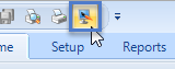
- Click the Design Mode icon in the Doors.NET client.
- Go to Setup >> Hardware Setup >> All - to display the hardware tree.
- Right-click the OSDP ENTRY reader and select OSDP >> Polling Disabled. This will prevent the EXIT reader from being detected as the ENTRY reader when it is connected.
- Connect the EXIT reader to the bus (the ENTRY reader should remain disconnected).
- In Doors.NET select the bus that the ENTRY reader is added to.
- In the hardware select ribbon bar, click on the Add NXT reader icon.
- A message will appear informing you of the address that will be assigned to the EXIT reader. Click YES to the message.
- The OSDP Exit reader will appear on the hardware tree beneath the ENTRY reader.
- Within a few seconds the EXIT reader should be online.
- Connect the ENTRY reader into the same bus as the EXIT reader.
- Verify Design Mode is still enabled.
- Right-click the ENTRY reader and select OSDP >> Normal Polling.
- Within a few seconds both readers should be online.
7.0 Auto-Discovery Change Address
The newer OSDP readers support 'auto-discovery' this will allow you to change the reader's address from the Doors.NET soft ware (again, this requires you to be logged into Doors.NET as a system administrator and you will need to momentarily enable Design Mode). Refer to the reader documentation for details about changing the reader's address if the reader does not support Auto-Discovery.
- Enable Design Mode (via the Design Mode icon):
- Select the reader in the hardware tree.
- In the reader properties, change the reader address number.
- Save the reader settings.
- Right-click the reader in the hardware tree and select OSDP >> Auto-Discovery.
- The reader will momentarily go offline. Once it is back online it will be configured with its new address.
8.0 OSDP Reader Supervision
Because the OSDP readers are fully supervised, if the reader is disconnected there will be an event displayed in live events.
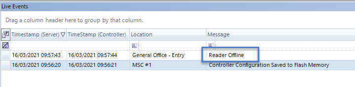
You can configure this event type to generate a sound alert at the PC or you could configure an e-mail or SMS message to be immediately sent out to a designated recipient.
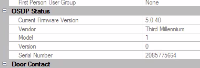
9.0 OSDP Status Information
- The Doors.NET software will detect the reader vendor, the model, the version number and the reader serial number (which you can view by selecting the reader in the hardware tree). The reader properties display on the right.
- Scroll down the reader properties and locate OSDP Status.
- The reader vendor and model details will be displayed.
10.0 OSDP Reader Firmware Upgrading
To be implemented in a future Doors.NET release.
11.0 Enabling OSDP Secure Channel on an OSDP Reader
- The following steps assume you have installed the HID Reader Manager app on your phone and have registered and verified your HID account.
- As well as enabling the OSDP Secure Channel, the app allows you to configure other OSDP settings, such as; the address number and OSDP baud rate.
- The steps may differ slightly for other OSDP vendors - refer to the reader vendor's documentation for specific OSDP Secure Channel setup instructions.
The following steps explain how to enable the OSDP Secure Channel on an HID Signo or iClass SE reader using the HID Reader Manager app.
- Ensure NFC or Bluetooth is enabled on your smart device (depending on which method you wish to use to connect to the reader).
- Log into the HID Reader Manager app (with your registered e-mail and password).
- Once connected, the reader summary will be displayed.
- Scroll down the reader details and select Detailed Configuration.
- If prompted, power-cycle the reader by physically disconnecting the reader terminal block from the controller.
- Select Communication Protocol.
- Scroll down and turn on the Secure Mode option.
Note: Near the OSDP Mode setting you will also see the reader address and OSDP baud rate. The default address is 00 and the default baud rate is 9,600. These are also the default address and baud rate settings in Doors.NET. - Select Add to Template then select Apply Selected Items.
- Within a few seconds the secure channel settings will be written to the OSDP reader.
- You must now go to the OSDP reader settings in Doors.NET and enable the OSDP Secure Channel option.
- You should also verify that the address and the baud rate matches what is displayed in the Reader Manager app.
- Once the reader status shows online in Doors.NET, the OSDP reader will be communicating with the NXT-MSC controller using the unique encryption key.
Related Articles
Doors.NET Hardware Browser Changes
1.0 Introduction From Doors.NET v5.2.0 and onwards, there is a slight difference in setting up a Gateway Node for wireless lock integration. Prior to v5.2.0, a gateway node would be added to a controller bus. From v5.2.0 and onwards, the gateway node ...Doors.NET v5.2.0 Release Notes
Doors.NET Release Notes - 01298-013 Rev. A Doors.NET v5.2.0 Software - 02635-013 Operating System Compatibility Doors.NET series 5 software IS COMPATIBLE with: Windows 8.1 Windows 10 - all versions Windows 11 - all versions Windows Server 2012 and ...Doors.NET - Network and Data Security and Encryption
1.0 Introduction This document explains what security measures are in place with Doors.NET to minimize the possibility of data being intercepted or an unauthorised intrusion on the network. The Doors.NET™ system encrypts the data between the ...NXT Exit Reader Setup
NXT Exit Reader Setup Keri NXT controllers with Mercury Firmware now provide an Entrance/Exit reader door control feature/configuration. This Entrance/Exit feature allows two readers to be wired into one bus on the NXT controller to control entrance ...Doors.NET - Door/Reader Settings
1.0 Introduction The Setup Doors process allows you to configure door operating parameters, view event history, audit changes, view current status, manually lock/unlock, configure reader type (as applicable), and mask/unmask certain door event types. ...