OTIS Destination Dispatch
1.0 Introduction
OTIS Destination Dispatch integration allows the Doors.NET software to integrate with an OTIS Destination Dispatch Elevator Control system via the use of Mercury LP4502 controllers, which in turn, communicate with the OTIS touchpad or touchscreen devices known as DECs. DEC Stands for 'Destination Entry Computer'.
Destination Dispatch allows a facility to optimize elevator travel to reduce travel and wait times. Being able to group passengers according to their travel destination and point them towards the appropriate elevators.
This integration allows you to control up to 64 OTIS DECs with a single LP4502 controller.
Notes:
- Additional Dual Door Modules will be required if you will not be using the DEC's embedded reader.
- Adding one or more Secondary LP4502 controllers will support up to 64 additional DECs per Secondary LP4502.
Keri Systems can only provide technical support for setting up the integration with the Doors.NET software.
This document explains the setup procedure for integrating Doors.NET with an existing OTIS Destination Dispatch System.
For typical Elevator Control, the configuration involves the use of physical controller relays. With OTIS Destination Dispatch there is no relay control and/or relay configuration. All the decision-making and processing is done through software on the OTIS Server. This considerably simplifies the setup and installation process and hardware requirements.
Destination Dispatch uses touchpad kiosks (otherwise referred to as 'DECs') to grant access and to determine which floor(s) the cardholder will go to. Each DEC has an embedded reader and the embedded reader is part of the DEC hardware.
Note:
All external (non-embedded) readers must be connected to the LP4502 either directly through an onboard reader port - or through an access control module, such as a Single-Door Module (MR50) or Dual-Door Module (MR52) or MR62e. It is advisable to first setup and verify the functionality of the reader as a standard reader and then converting the controller to OTIS Destination Dispatch.
2.0 Integration Functionality
- When a change is made in the Doors.NET client, such as: adding a new cardholder (and assigning access rights to one of the DECs), Doors.NET sends that data to the application server, the application server sends it to the gateway, then the gateway interacts directly with the LP-4502 primary controller.
- Cardholders are enrolled into the system as normal and their access rights are determined by their assigned access group.
- The LP-4502 has 2 x NICs (Network Interface Cards).
- The first NIC needs to be on the same subnet as the SCP/MSC gateway.
- The second NIC requires a USB-Ethernet adapter and should be on a separate, dedicated subnet with the OTIS Destination Subnet system.
- There is a message protocol that handles the data between the gateway and the LP-4502.
- There is a UDP protocol for the messages that flow between the LP-4502 and the OTIS Destination Dispatch Server.
- Typically it is only TCP/IP messages that are processed by the LP-4502 but with the Destination Dispatch integration, there are two different protocols: the TCP/IP message from the gateway and also the UDP messages going to the OTIS system/simulator.
Note: If additional LP-4502 controllers are being used (for more than 64 OTIS DECs, then the secondary LP-4502 controllers only require the use of their first NIC - (to communicate with the MSC gateway on the same subnet as the first LP-4502). Secondary LP-4502 controllers do not communicate with the Destination Dispatch System Server).
3.0 Supported Credentials
Most OTIS Destination Dispatch systems will typically make use of the readers that are embedded in the DEC. The embedded readers support a very wide range of credentials, but please contact your Otis representative for embedded reader documentation and supported credentials and specific reader types.
If the system requires the use of credentials which are not supported by the embedded reader, then an alternative option is to use readers which are compatible with the Mercury hardware - and physically connected to the LP-4502 - or to SDMs/DDMs.
4.0 Controlling More Than 64 OTIS DECs
A single LP4502 controller can handle up to 64 DECs - (62 DECs if using 2 physical readers utilizing the 4502’s onboard reader interface). A secondary 4502 controller is required if more than 64 DECs are necessary.
To support multiple LP-4502s (for more than 64 DECs), a Primary and a Secondary controller needs to be configured. The Primary LP-4502 will manage the communications to the OTIS Destination Dispatch Server (DDS). The Secondary LP-4502 will communicate through the Primary controller - This is achieved using an Over-Watch Controller Service. The LP-4502 has a plug-in package to install the Over-Watch controller service - this service is to be installed on the Primary LP-4502 controller only.
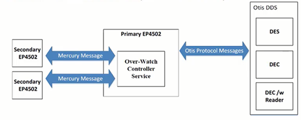
The Secondary controllers communicate through the Primary controller - there is no situation where the Secondary controllers communicate directly with the OTIS Server.
 For further information about the Overwatch controller service, refer to the following document:
Mercury Overwatch Application Note
IMPORTANT NOTE: Each separate bank of elevators will have its own OTIS DDS Server - plus a dedicated Primary LP4502. So for example a casino with three towers would have three OTIS DDS Servers, each with its own dedicated Primary LP4502.
5.0 Hardware Requirements
- Mercury LP-4502 controller - the LP-4502 has 2 x communication ports (an RJ45, NIC 1) and a micro USB port (NIC 2 - adapter required.)
- Secondary LP-4502 controllers (if more than 64 DECs will be controlled). Secondary LP-4502 controllers DO NOT use the second NIC (Micro USB port). Secondary LP-4502s only use NIC 1 to communicate with the Primary LP-4502 and the MSC SCP gateway.
- A PC is required for running the latest version of the Doors.NET software. A second PC is required for running the OTIS Destination Dispatch server.
- Optional external readers (wired into the LP-4502 or SDM/DDM modules) - If the embedded DEC readers are not compatible.
- Optional additional SDM/DDM modules - If the embedded DEC readers are not compatible.
5.1 Readers (Embedded Vs External Readers)
Out of the box, an LP4502 has a total of 64 possible reader device addresses, ranging from 0 to 63.
Each DEC uses up one LP4502 reader device address.
Each onboard reader uses up one LP4502 reader device address (unless onboard readers are disabled).
Each external reader uses up one LP4502 reader device address.
Example Scenarios
CASE 1:
LP4502 onboard readers DISABLED.
0 external readers assigned to DECs
You can add 64 DECs since each DEC only uses one reader device address
CASE 2:
LP4502 onboard readers DISABLED.
2 external readers assigned to DECs
You can add 62 DECs since the external readers use 2 reader device addresses so there's only 62 addresses left
CASE 3:
LP4502 onboard readers ENABLED
0 external readers assigned to DECs
You can add 62 DECs since the onboard readers use 2 reader device addresses so there's only 62 addresses left
CASE 4:
LP4502 onboard readers ENABLED
2 external readers (from an additional DDM, not the onboard readers) assigned to DECs
You can add 60 DECS. The two onboard readers use 2 reader device addresses; the two external readers use another 2 reader device addresses; only 60 addresses left.
6.0 Licensing Requirements
The Destination Dispatch feature needs to be enabled on your Doors.NET license. The following steps explain how to check that it is enabled.
- Open the Doors.NET License Manager (Windows Start menu >> Doors.NET >> License Manager).
- Select the Application Server listed on the left.
- Click on the License tab.
- Scroll down the list of licensed features until you locate Options.
- Ensure Destination Dispatch is set to Otis. As highlighted.
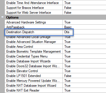
Note: Otis is the only Destination Dispatch vendor currently supported. If Destination Dispatch is not enabled then you would need to contact Keri Inside Sales.
7.0 Mercury LP-4502 Controller Setup
Refer to Mercury LP-4502 Security Installation Guide and the Doors.NET LP4502 controller setup guide for information about installing the LP-4502 controller and getting it online in Doors.NET.
8.0 LP-4502 Controller Configuration
The following section explains how to configure the LP-4502 controller for the Destination Dispatch functionality:
Once the LP-4502 controller has been setup in Doors.NET and is online, it is ready to be configured. To configure the controller for Destination Dispatch, you will need to have Advanced View enabled in the hardware properties.
- From within Doors.NET, go to the hardware tree (Setup >> Hardware Setup >> All).
- Select the controller on the hardware tree.
In the controller properties, ensure the controller is online.
Also in the controller properties, scroll down to the General settings.
From the Controller Function drop-down list, select 'OTIS Destination Dispatch'.

When you select OTIS Destination Dispatch you will almost immediately see a message stating that a new Destination Dispatch panel will be created and will be added to the hardware tree. Click Yes to the message.
Save the controller settings.
You will be prompted to reset the controller, so click Yes to this.
Once the controller is reset and back online, double-click to expand the LP-4502 in the hardware tree.
You will see an additional module that will be named DEC Collection.
The new module is now ready for configuration.
9.0 Add a Facility
- From within the software, click on Setup >> Hardware Setup >> All to display the hardware tree.
Highlight Facilities in the hardware tree.
Click the Add Facility icon.

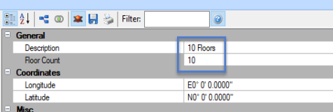
Highlight the new facility then give it a new description.
Specify how many floors the facility will have. If there are front and rear doors then floors should be doubled even if all floors do not have rear door access. 5 floors with front and rear access will be a total of 10 floors.
- Click to expand the floor names. Enter new names for the floors if you need to.
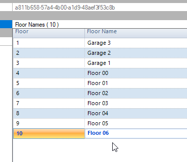
- Save the facility settings.
10.0 Assign the Facility to the LP4502 Controller
The next step is to assign the facility to the controller to determine which floors will be serviced by the controller.
- Select the controller in the hardware tree.
- In the properties on the right, locate the Elevator Control setting.
- Select the recently created facility.
- Choose which floors from the facility this controller will support.
- Save the controller settings.
11.0 Set the Correct Elevator Cab Door Type
Also in the reader properties you should set the type of Elevator cab door type.
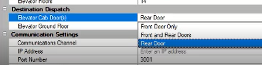
There are 2 choices, the option is either Front Door Only or Front and Rear Doors.
*If using Front and Rear door the Facility floor count should be double the actual number of floors. If 5 floors then it should be 10 floors. Selecting Front and Rear Doors will display Front and Rear in the floor descriptions on the Elevator Access Groups screen.
12.0 Set the Correct Ground Floor Number
Because not all buildings are designed the same, you will need to define which facility floor number is the ground floor. Many buildings have multiple basement levels or underground parking levels. For example, the designated ground floor might be number 5 and there may be 4 other lower-ground level floors.
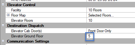
If you don't have any floors below the ground floor level, then the ground floor would be defined as #1 (the first floor in the list). This setting is to ensure that in live events the messages will display the correct floor number.
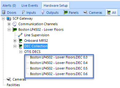
13.0 DEC Collection Module Configuration
[The DEC Collection panel is what the OTIS DECs are added to]. DEC stands for 'Destination Entry Computer'.
- Select the new DEC module to view its properties on the right.
- You can change the description from the default of 'Dec Collection'. It may be more appropriate to rename it to something like 'DEC Panel' or 'DEC Control Panel'.
- This panel is the onboard DDM for the OTIS Destination Dispatch System (OTIS DDS).
14.0 Add OTIS DECs
Notes:
- You can add up to a maximum of 64 DECs.
- If external readers are added to the DEC this will reduce the total count of DECs.
The OTIS DECs are added to the LP-4502 module located on the hardware tree in Doors.NET.
- Select the new 'DEC Collection' module in the hardware tree.
- From the ribbon bar, click on the OTIS DEC icon.
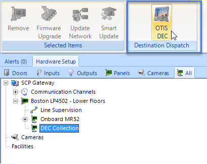
A new OTIS kiosk will be added to the hardware tree.
Click to add as many as the system requires.
15.0 Configure the DEC Properties
Note: Ensure Advanced View is enabled.
- Select a DEC from the hardware tree and the kiosk properties will be displayed on the right.
- Because a DEC is very different to a reader, certain settings are hidden (such as door contact, RTE input and strike output) as these do not apply to a touchpad DEC.
- Scroll down the properties grid and locate the Destination Dispatch properties.
- IP Address - Each DEC has a programmed IP address which needs to be entered.
- External Readers - You don't need any external readers if the cards you are using are supported by the DECs embedded reader.
- An external reader can be defined if the cards you are using are NOT supported on the embedded reader. You can define one or two external readers per DEC - these external readers are wired into the LP4502 or SDMs/DDMs.
- Note: For additional external readers you would need to add additional SDM or DDM modules connected to the LP4502.
- Public Floors Elevator Access Group - Defines floors which don't require a valid card read to get to that floor. You would just use the touch pad DEC to select the floor you wish to go to and the DEC calls the cab for you. Commonly, for many buildings there will be a set of public access floors that would apply to all DECs, this would typically include the ground floor and maybe an observatory or canteen that anyone can access.
- The System Mode field determines the operating mode of the DEC. The DEC supports 4 different operating modes, which are as follows:
- - Mode 1 - Default Floors- Cardholder presents a credential to the LP4502 reader... If there is a default floor assigned to the credential and authorized to access that floor at the time the credential is presented, then access will be granted and the cab will be called to take you to that floor. In Mode 1 you can also select a floor first, if it is a public floor then a cab will take you to that floor. If it is not a public floor, then you will need to present your card.
- - Mode 2 - Access to Authorized Floors - Cardholder presents a credential to the LP4502 reader. If the credential contains active access levels, the DEC will allow you to select a floor. The DEC will inform the cardholder if the selected floor is authorized.
- - Mode 3 - User Entry of Destination - The cardholder will select a floor on the DEC touch pad. Next, the user presents a credential to the LP4502 reader. The DEC will inform the user if the selected floor is authorized.
- - Mode 4 - Default floor or Entry of Destination - This is a combination of modes 1 and 2. The cardholder presents a credential to the LP4502 reader. Within a specified time-out period set on the DEC, the cardholder may select a floor. If a floor is not selected, the DEC will inform the user if the cardholder is authorized to access the default floor. If a floor is selected, the DEC will inform the user if the cardholder is authorized to access the selected floors.
16.0 Setup Elevator Access Groups
The elevator access groups determine which floors the cardholders can gain access to after presenting their credential to the reader at the DEC. The OTIS Destination Dispatch access groups are setup in two sections (the Elevator Access Groups and then the standard Access Groups screen). It is the standard access groups which are then assigned to the cardholders. Elevator access groups are NOT directly assigned to cardholders.
Note: Public Floors - Here you should also create any public floor elevator access groups (which can then be assigned to the DEC).
Public floors do not require a valid card to gain access to those floors.
- In Doors.NET, go to Home >> Elevator Groups.
- Click the Add icon on the ribbon.
- Change the description to something appropriate to your site. Press Enter and click Yes to confirm the new description.
- Highlight the new group.
- In the Floors list in the properties section, highlight the floors you wish to add. Click on the first floor and then drag the mouse down to the last selection, or select the first, press the shift key, and then select the last.
- Highlight a time schedule to assign to the group.
- When all 3 elements that make up the access group are highlighted, the Assign button on the ribbon becomes active.
- Click Assign to create the elevator access group.
- If a cardholder requires access to various floors at different times of day then these floors and time schedules would all need to be added to the same elevator access group. This is even the case if the floors exist in different facilities. As you can see in the following image, multiple floors have been defined and each floor follows a certain time schedule. If you then need to restrict the time when access is allowed to a certain floor you would then merely need to adjust the time schedule itself.
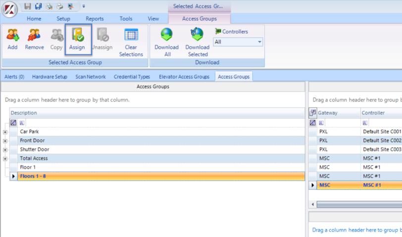
- A cardholder cannot directly be assigned an 'elevator access group', so this group will need to be added to the general system access groups. From the Home tab click Access Groups.
- Click the Add button.
- Give the new group an appropriate description and save it.
- Select the new Elevator Access Group.
- Select the elevator DEC.
- Select the Elevator Access Group. You do NOT need to highlight a time schedule on this page because it has already been defined in the Elevator Access Group setup page.
- Click the Assign button to complete the elevator access group setup.
17.0 Assign Access Rights
Once Elevator access groups are created, they can be assigned to cardholders in the same way that standard access groups are assigned:
- In Doors.NET, go to Home >> Cardholders.
- Open an existing cardholder record (or enroll a new cardholder if this is a brand new system).
- Click on the access rights tab.
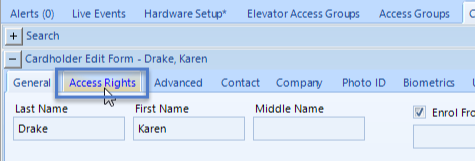
Place a check mark against the elevator access group you wish to assign the cardholder.
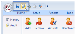
- Save the cardholder record.
18.0 Edit Destination Dispatch Cardholder Information
This is the last step of the setup process. In each of the cardholder records you will see a Destination Dispatch tab. Click this tab to see the additional settings.
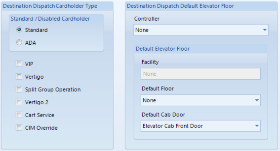
- Standard or ADA - The cardholder can be either standard or ADA.
- Other cardholder settings - To be added
- Destination Dispatch Default Elevator Floor - Select the controller to which the cardholder's default floor is located.
- Default Elevator Cab Door - If you have both front and rear cab doors then here you would specify which one is the default door
18.1 Destination Dispatch Cardholder Types
The following cardholder types can be combined at times to fulfill a wide variety of purposes, mostly centered around controlling user access to a particular elevator car, or set of cars.
VIP Operation: VIP Operation provides exclusive priority service through dedicated VIP elevators. When activated, it sends an empty car to the VIP’s floor of origin and then proceeds non-stop to the destination floor requested. It can be initiated by a pass code entry on a Compass® 360 fixture, a credential presentation to an integrated Security system or from EMS Panorama 2.0.
Vertigo Operation: Vertigo operation allows for pre-determined elevator(s) to be assigned to a given passenger’s request. The elevator selection for vertigo operation is typically driven by a preferred physical characteristic of certain elevators within a building. The passenger’s destination floor request would initiate this operation with a pass code or by providing a credential on a Compass® 360 fixture that is integrated with a building security system.
Split Group Operation: Split Group Operation allows a single elevator bank to be divided into independent operating groups. A typical application would be non-tenant staff in a building using an assigned elevator group while assigning tenant employees to a separate group.
Cart Service Operation: Cart service is generally used in a hotel or hospital environment where the elevator may be used for moving large capacity conveyances such as laundry carts, food carts, or stretchers. In these cases, the elevator car could potentially be filled when a single destination floor request is made to it. To ensure that a properly loaded elevator car is assigned for such scenarios, a pass-code associated with cart service may be entered at the Compass® 360 fixture. Once this request is made, an elevator that has enough capacity to accommodate the passenger and cart will be assigned to the destination floor request. If no such elevator car is available, Compass® 360 will assign an elevator car that has the most available capacity to serve the Cart Service Floor request.
Compass Inter-Floor Matrix Operation: Compass servers can be programmed with “Compass Inter-Floor Matrix Operation” – this allows for certain inter-floor travel restrictions to prevent one tenant from going to another restricted floor within the building. It is not an example of floor level access control, but provides some segmentation of the building to prevent tenants from going to mechanical floors, or something similarly simple. It is not typically used in conjunction with an actual Access Control system (such as Doors.NET). However, the CIM Override bit will apply the override of that matrix for the user’s call, effectively bypassing any existing segmentation.
Related Articles
Doors.NET v5.1.0 Release Notes
Doors.NET Release Notes - 01298-012 Rev. A Doors.NET v5.1.0 Software - 02635-012 OPERATING SYSTEM COMPATIBILITY Doors.NET software IS COMPATIBLE with: Windows 8.1 Windows 10 - all versions Windows 11 - all versions Windows Server 2012 and 2012 R2 ...Doors.NET v6.1.0 Release Notes
What's New in Doors.NET v6.1.0 Doors.NET Release Notes- 01298-017Rev. A Doors.NET v6.1.0 Software- 02635-017 Operating System Compatibility Doors.NET series 6 software IS COMPATIBLE with: Windows 10 LTSC or LTSC Enterprise Windows11- all versions ...Doors.NET v5.3.0 Release Notes
Doors.NET Release Notes - 01298-014 Rev. A Doors.NET v5.3.0 Software - 02635-014 Operating System Compatibility Doors.NET series 5 software IS COMPATIBLE with: Windows 8.1 Windows 10 - all versions Windows 11 - all versions Windows Server 2012 and ...What's New in Doors.NET (v6.0.0)
Operating System Compatibility Doors.NET series 6 software IS COMPATIBLE with: Windows 10 - all versions Windows 11 - all versions Windows Server 2012 and 2012 R2 Windows Server 2016 Windows Server 2019 Windows Server 2022 Windows Server 2025 All ...Doors.NET v5.4.0.8 Release Notes
Doors.NET Release Notes - 01298-016 Rev. A Doors.NET v5.4.0.8 Software - 02635-016 Operating System Compatibility Doors.NET series 5 software IS COMPATIBLE with: Windows 8.1 Windows 10 - all versions Windows 11 - all versions Windows Server 2012 and ...