NXT-MSC - I/O Control Using MR16IN and MR16OUT Modules
1.0 Introduction
Notes:
You must have a Doors.NET Professional license to see the options to add the MR16IN or MR16OUT to NXT-MSC.
- If you are using an MR16IN or an MR16OUT module on a bus, you won't be able to use any other RS-485 device on that bus (such as an NXT reader, a 4x4 module or an NXT-RIM) an NXT reader is added, by default, so that will first need to be deleted.
Each bus can support up to 32 panels (either MR16IN or MR16OUT or a combination of both). The first controller added to the bus will be configured as address 0 in the controller properties.
The maximum number of MR modules for an NXT-MSC 2D controller is 64. For an NXT-MSC 4D controller the maximum is 96.
The series 2 MR16 modules (green-coloured PCBs) support 2-wire or 4-wire RS-485, whereas the series 4 (red PCBs) only support 2-wire RS-485. Ensure the J3 jumper is correctly configured for 2-wire RS-485.
2.0 NXT-MSC Controller to MR16IN/MR16OUT Wiring
2.1 Wiring at the NXT-MSC Controller
- You should not power the MR16IN or MR16OUT module from the controller's bus. The MR16IN or MR16OUT module should have its own dedicated power supply.
- You should connect the RS-485 shield drain to the earth-ground at the NXT-MSC controller only (to prevent ground loops). The shield drain can connect to the earth at pin 3 of the power connector or the ground lug screw as shown in the above diagram.
2.2 Wiring at the TB10 connector of the MR16IN/MR16OUT Module

2.3 RS-485 Wiring Specification
- The recommended cable type for the RS-485 connection (between the NXT-MSC controller and the downstream MR16 modules) is Belden 9501 (or equivalent) - this is a 1-pair shielded, stranded, twisted cable. AWG 24 wire or larger (note that increasing the wire gauge does not increase the total network length) - The total network length is 4,000 feet/1,000 meters.
- The RS-485 wiring between MR16 modules is a daisy-chain connection.
3.0 Set the MR16IN/MR16OUT RS-485 Address
The S1 switch on the MR16IN or MR16OUT module is used to set the RS-485 address and the controller's baud rate. When using Doors.NET v5.2.0 and greater, the first MR16 module that you add to the bus, by default, will be configured in the software as address 0 and the default baud rate is set to 38,400bps.
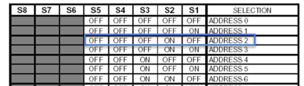
The comm address will automatically be set in the software based on the following rules:
- The first module to be added to the controller's bus will be configured in the software as address 0.
- Each of the controller buses can have up to 32 MR16 modules.
- If you add modules to a different bus, again, the first module will be address 0 (because it will be a second, completely separate RS-485 network).
This allows you to have MR16 modules on one of the controller buses and other panel types on a different bus. The address scheme is so the other buses are not affected. However, once a bus has been configured for Mercury hardware (MR16IN and MR16OUT modules), these will be the only hardware type that you can add to that bus.
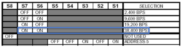
4.0 Set the MR16IN/MR16OUT RS-485 BAUD Rate
The S1 DIP switch is also used to set the RS-485 BAUD rate to 38,400 (using S6 and S7 in the ON position).
5.0 Add an MR16IN or MR16OUT Module
Notes:
- This section assumes you already have an NXT-MSC controller setup and online.
- These instructions assume you are using Doors.NET v5.2.0 or later.
5.1 Remove the default Keri NXT reader from the controller's bus
- In the Doors.NET user interface, go to Setup >> Hardware Setup >> All (to display the hardware tree).
- All controllers on the system will be displayed on the hardware tree.
- Double-click the controller that the MR16 module will be added to.
- Expand the specific bus that the MR16 is wired to.
- Select the default reader located on that bus (by default an NXT 3R reader is added).
- Click the Hardware Browser tab near the top of the screen.
- Click the Remove button.
- The NXT reader will be removed from the bus.
5.2 Set the correct protocol on the controller's bus
- Select the name of the bus on the hardware tree.
- The bus properties will now be displayed on the right-side of the screen.
- Locate the 'Protocol' setting (by default it is set to Keri Systems).
- Use the drop-down menu to change the protocol to Mercury Security.
- You will be prompted to perform a memory reset on the control. Click YES to go ahead with the controller memory reset.
- Wait for the controller to come back online.
5.3 Add the MR16 Module to the controller's bus
- Select the same controller bus again on the hardware tree.
- From the hardware select ribbon bar click on either MR16IN or the MR16OUT icon.
- You can use the Quantity drop-down menu to select to add multiple MR16IN modules or multiple MR16OUT modules.
- You can also change the default description for the new module(s).
- Click the ACCEPT button to add the new module to the hardware tree.
- Select the new MR16 module on the hardware tree.
- You will see the module's properties on the right.
- By default, the first module to be added to the bus will be addressed as 0. Also by default, the default baud rate is 38,400. Therefore, if the module's S1 switch is setup with address 0 and baud rate 38,400 the module should come online after a few seconds.
Note: When adding the MR16IN or MR16OUT modules, they can be addressed in any order. The only requirements is that each module has the unique address that is displayed in the module properties when it is added to Doors.NET.
7.0 MR16IN Input Properties
- Go to Setup >> Hardware >> All.
- Expand the MR16IN module which has been added to the hardware tree.
- Double-click inputs and you will see a list of all 16 of the module's inputs.
- Select any of the individual inputs and the input properties will be displayed on the right.
Note: An MR16IN module also has 2 x general-purpose outputs as well as its 16 inputs. - Refer to the general Setup Inputs section for further details about input settings.
8.0 MR16OUT Output Properties
- Go to Setup >> Hardware >> All.
- Expand the MR16OUT module which has been added to the hardware tree.
- Double-click outputs and you will see a list of all 16 of the module's outputs.
- Select any of the individual outputs and the output properties will be displayed on the right.
Note: An MR16OUT module only has its 16 outputs. It does not have any general-purpose inputs. - Refer to the general Setup Outputs section for further details.
9.0 Basic I/O Linkage
You can use basic I/O linkage (input/output linkage) to configure an available input to control a single output. For example; the input may be the door contact of a door that does not have access control. You can program an output (that may be an external LED) to be on whenever the door is physically opened and then the external LED goes off when the door is closed.
- Refer to the Basic I/O Linkage Actions section for further details.
Related Articles
NXT-MSC 2D Elevator Control Wiring
NXT-MSC Elevator Controller Wiring to NXT 4x4 ModulesNXT-MSC 2D Data Sheet
NXT-MSC (Mercury-Powered) 2-Door Controller Data Sheet (attached)NXT-MSC 4D Data Sheet
NXT-MSC (Mercury-Powered) 4-Door Controller Data Sheet (attached)NXT-MSC v1.296 Firmware Release Notes
1.0 NXT-MSC Controller Firmware Release MSC controller firmware v1.296 addresses the following issue: • Corrects 4x4 and GIOX elevator control relay mapping issues. NOTE: If you are using MSC controller firmware v1.294 and are NOT using elevator ...NXT-MSC Controller - Advanced and Extended Features
1. 0 Introduction The NXT-MSC (Mercury-Powered) controller is programmed with the firmware of a Mercury EP1502 controller. It has all the standard and advanced functionality of an EP1502, such as: temporary cards (by use count, number of days or ...