1.0 Important Note:
Keri Public Statement on the Amazon Key
Keri Systems, Inc. has updated its policy regarding the integration of
Amazon devices with Keri Systems controllers. We are pleased to inform you that Amazon has now provided official installation
documentation for Keri products within their installation app. As a result, Keri Systems
will allow Amazon devices to be installed alongside Keri controllers when following
the guidelines and best practices provided by Amazon. This change reflects our commitment to supporting secure and flexible access solutions
that enhance customer convenience, including use cases such as Amazon delivery access. Please note the following: - Installers must follow Amazon’s official documentation and procedures for
installing Amazon devices with Keri hardware. - Keri recommends that all installations be performed by trained professionals
familiar with both Keri and Amazon device requirements. - Any damage caused by improper installation or failure to follow approved
documentation may still void the controller warranty. - Responsibility for any security concerns or access control changes introduced
by the integration rests with the Building Owner or Manager.
Keri Systems remains dedicated to providing robust access control solutions.
We will continue to monitor and evaluate integrations to ensure the safety
and satisfaction of our customers. |
2.0 Wiring Diagram
3.0 Specifications:
Unit Dimensions
• PXL-250/PXL-500/PXL-510 controller PCB with an SB-593 Satellite Board (with or without
an LCD-1 Alpha/
Numeric Display):
- 7.25 inches high by 6.00 inches wide by 1.75 inches deep, including wiring connectors
- (18.45 cm by 15.25 cm by 4.45 cm)
• Enclosure
- 9.70 inches high by 8.20 inches wide by 2.60 inches deep
- (24.65 cm by 20.85 cm by 6.60 cm)
Operating Temperature/Humidity Range
• 0°F to 140°F (-18°C to 60°C)
• 0% to 90% Relative Humidity, non-condensing
Controller with Satellite Board Power Requirements
• 12 VDC @ 1 Amp
Current Draw
• maximum current draw 270 mA for a controller plus reader current draw (refer to Table 1 for Reader current draw)
• 120 mA max for a PXL-250/PXL-500/PXL-510 Controller
• 150 mA max for an SB-593 Satellite Board
Table 1: Reader Current Draw
Reader Type
| MS-3000
| MS-4000 | MS-5000 | MS-7000 |
Current Draw
| 50 mA | 50 mA | 100 mA | 200 mA |
Output Relay Contact Rating
- 1 Amp @ 24 VDC
Input Device Configuration
• Door Sense normally closed
• Request to Exit normally open
• Global Unlock normally open, or
Auxiliary RTE A-Door normally open
Cable Requirements
• two conductor, AWG 22 or a larger gauge for all input connections
• two conductor, AWG 18 or a larger gauge for all output connections
Note: The Lock Output relay may require a heavier gauge of wire depending upon the
current demands of the lock and
the length of the lock wiring run.
4.0 When Installing Satellite Boards
DO
• route cables in accessible areas for ease of maintenance
• add transient suppression across electric devices attached to a satellite board output
• use an isolation relay (Keri Systems P/N IRP-1) if attaching to a parking gate, a turnstile, or any application using a
large electric motor
• for a single door application, install the door's reader to the TB-5, "A" reader connection on the controller
• for a two door application, install the primary door's reader to the TB-5, "A" reader connection on the controller and
install the secondary door's reader to the TB-6, "B" reader connection on the controller
DO NOT
• stretch or over-tension cables
• route cables over sharp objects
• let cables or wires get tangled
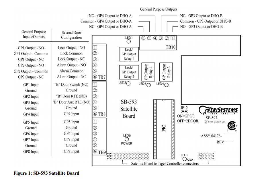
5.0 Jumper Settings
JP12 - Configures the Satellite Board (see Figure 2).
• Jumper across JP12, pins 1 and 2, configures the Satellite board for general purpose inputs and outputs.
• NO jumper across JP12 configures the Satellite board for second door control with additional inputs and outputs.
When the Satellite board is configured for second door control, the primary door must be connected to the "A" reader
(TB-5 on the PXL-500/PXL-510 controller board) and the secondary door must be connected to the "B" reader (TB-6
on the controller board).
6.0 Board Installation
Perform the following steps to install an SB-593 Satellite Board on a PXL-250, PXL-500/PXL-510, or PXL-500G-1
controller. The SB-593 Satellite Board comes with two sizes of stand-offs. Due to changes made to the relays, some PXL
controllers will require the use of taller stand-offs.
• The smaller stand-offs are to be uses with PXL-500 controllers.
• The taller stand-offs are to be used when the Satellite Board is connecting to the new PXL-500-1 or PXL-500G-1
controllers.
Installation of these stand-offs are done exactly as before.
1. Turn the controller's power OFF.
2. Line up the upper left-hand corner of the Satellite PCB with the controller PCB.
3. Line up the stand-offs in the top two corners of the Satellite PCB with corresponding mounting holes in the controller
PCB.
4. Align the Satellite Board’s connector pins to the PXL mounting holes.
Note: If you are installing the SB-593 (which has two rows of connector pins) on a PXL-250 controller (which has one
row of mounting holes) it does not matter which row of connector pins are inserted in the mounting holes.
5. Gently press the two boards together with each stand-off into its mounting hole and with the connector pins meshing
together with their mounting holes.
6. Turn the controller’s power ON.
7. If the P2 mounting holes have the PXL J2 connector pins inserted correctly, the Power LED6 will illuminated and
remain so as long as the connection continues and power is supplied to the unit.
8. If the P3 mounting holes have the PXL J3 connector pins inserted correctly, the SDA LED5 will flicker and continue
to do so as long as the connection continues and power is supplied to the unit.